
Installation Instructions


Installation and Operator Handbook Installation Instructions
AMX–MA–00653 Issue 0.03 (USA) 10
3.5.4.3 Transceiver Module
To install the Transceiver Module:
1. Carefully insert the Transceiver Module into its position from the front of the cabinet by aligning the
guide rails and pushing home until the backplane connector is correctly mated and the panel is flush
with the adjacent panels.
2. Using a medium sized flat-bladed screwdriver, secure the Module using the two captive collar screws.
Do not over-tighten.
3. If two Transceiver Modules are supplied repeat for the other module.
3.5.4.4 Controller Module
To install the Controller Module:
1. Carefully insert the Controller Module into its position from the front of the cabinet by aligning the
guide rails and pushing home until the backplane connector is correctly mated and the panel is flush
with the adjacent panels.
2. Using a medium sized flat-bladed screwdriver, secure the Module using the two captive collar screws.
Do not over-tighten.
3.5.4.5 Interface Module
To install the Interface Module:
1. Carefully insert the Interface Module into its position from the rear of the cabinet by aligning the guide
rails and pushing home until the backplane connector is correctly mated and the panel is flush with the
adjacent panels.
2. Using a medium sized Phillips screwdriver, secure the Module using the two captive screws. Do not
over-tighten.
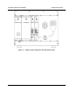
3.5.4.6 Loudspeaker Panel and Microphone
A DRB-25 configured with only one transceiver may have a Loudspeaker Panel, (or a Loudspeaker Panel and
microphone) installed in place of Transceiver 2 and its associated PA and power supply.
To install the Loudspeaker Panel and microphone:
1. The panel is installed on the right hand side of a single channel DRB-25 in place of Transceiver 2. An
internal cable is connected from the rear of the loudspeaker panel to the connector marked “TR1
Audio” on the DRB-25 backplane adjacent to Transceiver 2.
2. Carefully align the panel and using a medium sized flat-bladed screwdriver secure the panel using the
six captive collar screws.
3. If the panel is supplied with a microphone, the cable is connected to the Transceiver 1 front panel
audio connector (RJ45).