
Installation Instructions


Installation and Operator Handbook Installation Instructions
AMX–MA–00653 Issue 0.03 (USA) 6
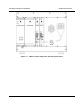
Figure 3-1 DRB-25 Rack Mounting Arrangement
3.5.3 Configuring DRB-25 Identity (Box ID)
An 8-way DIP switch on the backplane adjacent to Transceiver 2 enables a Box ID to be set for each DRB-25.
The switch is accessed from the front of the unit with the modules removed. A total of 256 identities are
available.
The Box ID is used by each Transceiver to determine its default settings on power-up. Transceiver modules
can be programmed with up to 512 operating channels, and the default operating channel for each Transceiver
is determined by the DRB-25 Box ID as detailed in Appendix A Table A-1.
DRB-25 Box ID settings may be defined in a plan that covers all DRB-25 units in the network. The Box ID is
also used by the Controller Module for network management purposes to enable it to identify itself within a
network.
The default factory setting is a box identity of zero.
To set the DIP switches:
1. LOCATE the DIP switch on the upper right of the backplane, through the front of the DRB-25 case
without the plug in modules fitted.