
Installation Instructions


Installation and Operator Handbook Installation Instructions
AMX–MA–00653 Issue 0.03 (USA) 9
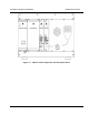
Figure 3-4 DRB-25 Rear Module Positions
3.5.4.1 Power Supply Module
To install the Power Supply Module:
1. Carefully insert the Power Supply Module into its position from the front of the cabinet by aligning the
guide rails and pushing home until the backplane connector is correctly mated and the panel is flush
with the adjacent panels.
2. Using a medium sized flat-bladed screwdriver, secure the Module with the four captive collar screws.
Do not over-tighten.
3. If two Power Supply Modules are supplied, repeat for the other module.
3.4.4.2 Power Amplifier Module
To install the Power Amplifier Module:
1. Locate the coax lead with a right-angled N-type connector. Stretch the lead out of the box and partially
insert the Power Amplifier into its card slot. Attach the N-type connector to the mating connector on
the Power Amplifier, then carefully insert the Power Amplifier Module fully into position from the
front of the cabinet. Push the module home so that the backplane connector is correctly mated and the
panel is flush with the adjacent panels.
2. Using a medium sized flat-bladed screwdriver, secure the Module using the four captive collar screws.
Do not over-tighten.
3. If two Power Amplifier Modules are supplied, repeat for the other module.