
User Manual
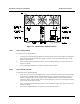


Table Of Contents
- 3 INSTALLATION INSTRUCTIONS
- 3.1 GENERAL
- 3.2 SAFETY PRECAUTIONS
- 3.3 SITE REQUIREMENTS
- 3.4 DELIVERY AND UNPACKING
- 3.5 INSTALLATION
- 3.6 CONNECTIONS
- 3.6.1 Grounding Strap
- 3.6.2 AC Power
- 3.6.3 DC Power
- 3.6.4 Antenna Cabling
- 3.6.5 External Interfaces
- 3.6.5.1 Transceiver Module Audio Connector
- 3.6.5.2 Transceiver Module Programming Connector
- 3.6.5.3 Controller Module Serial Data Connector
- 3.6.5.4 Radio Serial Data
- 3.6.5.5 Analog Line Connection
- 3.6.5.6 RS-485 serial data
- 3.6.5.7 Ethernet
- 3.6.5.8 General Purpose Input/Output Lines
- 3.6.5.9 External 10 MHz reference source
- 3.6.5.10 Standby power
- 3.6.5.11 -48 V DC input

Installation and Operator Handbook Installation Instructions
AMX–MA–00653 Issue 0.02 (USA) 17
Pin Function
12 General purpose input 6: +
25 General purpose input 6: -
13 Ground
Transmit disable inputs: When the + input is connected to +12 V and the - input to ground the relevant
transmitter is disabled.
Antenna relay outputs: Ensure that 4 links are present on Interface Module XM3. When the radio PTT is
active, the + output is connected to +12V, the - output is connected to ground
3.6.5.9 External 10 MHz reference source
Function: Provides 10 MHz input. When present automatically used in preference to internal 10
MHz reference
Located: Interface Module
Label: REF IN
Electrical: Level between 450 mV peak-peak and 4v peak-peak, impedance 50 Ohm
Connector: BNC
Pin allocation:
Pin Function
Inner External reference input
Outer Ground
3.6.5.10 Standby power
Function: Maintain internal reference oscillator during power outages.
Located: Interface Module
Label: STDBY IN
Electrical: 12 V DC (+/- 5%) input, max. current 1A
Connector: 2 pin (male). Mating plug: Phoenix Contact MSTB 2.5/2-ST-5.08
Pin allocation:
Pin Function
Upper +12 V DC ground (0 V)
Lower +12 V DC input
3.6.5.11 -48 V DC input
Function: Provides –48 V DC input for E/M signaling
Located: Interface Module
Label: -48 V DC
Connector: 2 pin (male) Mating plug: Phoenix Contact MSTB 2.5/2-ST-5.08
Pin allocation:
Pin Function
Upper -48 V DC ground (0 V)