
User Manual


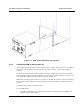


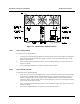

Table Of Contents
- 3 INSTALLATION INSTRUCTIONS
- 3.1 GENERAL
- 3.2 SAFETY PRECAUTIONS
- 3.3 SITE REQUIREMENTS
- 3.4 DELIVERY AND UNPACKING
- 3.5 INSTALLATION
- 3.6 CONNECTIONS
- 3.6.1 Grounding Strap
- 3.6.2 AC Power
- 3.6.3 DC Power
- 3.6.4 Antenna Cabling
- 3.6.5 External Interfaces
- 3.6.5.1 Transceiver Module Audio Connector
- 3.6.5.2 Transceiver Module Programming Connector
- 3.6.5.3 Controller Module Serial Data Connector
- 3.6.5.4 Radio Serial Data
- 3.6.5.5 Analog Line Connection
- 3.6.5.6 RS-485 serial data
- 3.6.5.7 Ethernet
- 3.6.5.8 General Purpose Input/Output Lines
- 3.6.5.9 External 10 MHz reference source
- 3.6.5.10 Standby power
- 3.6.5.11 -48 V DC input

Installation and Operator Handbook Installation Instructions
AMX–MA–00653 Issue 0.02 (USA) 7
2. Using a screwdriver or pen, set the eight sections of the DIP switch to the desired Box ID, according
to and the intended DRB-25 Box numbering plan.
3. The Switch 1 (LSB) is the top switch; Switch 8 (MSB) is the lower switch. OFF is to the left, ON is to
the right.
3.5.4 Installing the Modules
Refer to the following figures (Figure 3-2, Figure 3-3 and Figure 3-4) to identify the correct position for each
module within the DRB-25 cabinet. Install the supplied modules as detailed in the following paragraphs.
Figure 3-2 DRB-25 Front Module Positions