
User Manual

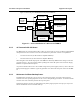


Table Of Contents

Installation and Operator Handbook Equipment Description
AMX–MA–00652 Issue 0.02 (USA)
2
2 EQUIPMENT DESCRIPTION
2.1 INTRODUCTION
DRB-25 equipment consists of modular hardware which is easily installed as a desktop cabinet, floor-mount
cabinet or into standard 19 inch racks.
The DRB-25 chassis and its component modules are described in the following paragraphs.
2.2 POWER SOURCE OPTIONS
2.2.1 AC Power Supply
The DRB-25 may be powered from the 240 or 110 V AC power supply via one or two Power Supply
Modules. Figure 2-1 shows the power distribution of an AC powered DRB-25.
7 V
12 V
Option for Second Channel
12V DC
Standby
Power
110/240 V
AC Supply
Switch
Power Supply
Module 1
System
PSU
Fans
Power Supply
Module 2
Power Amplifier 2
Power Amplifier 1
Transceiver Module 1
Transceiver Module 2
Controller & Interface
Modules
Figure 2-1 Power Distribution of an AC powered DRB-25
2.2.2 DC Power Supply
The DRB-25 may be powered from 12 or 24 or 48 V DC power supplies via one or two DC/DC Power
Supply Modules. Alternatively, the DRB-25 may be powered directly from DC power sources as follows:
• 12 V DC to 13.8 V DC (for 60 watt Power Amplifier Modules).
• 24 V DC to 28 V DC (for 125 watt Power Amplifier Modules).
Note that the RF output power of the DRB-25 is derated by 3 dB if the DC voltage is at the low end of the
range (i.e. at 12 or 24 V DC). When operating from a direct DC power source the Power Supply Modules are
replaced with blank panels.