
User Manual

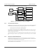


Table Of Contents

Installation and Operator Handbook Equipment Description
AMX–MA–00652 Issue 0.02 (USA)
3
Figure 2-2 shows the power distribution of a DC powered DRB-25.
7 V
12 V
Option for Second Channel
12V DC
Standby
Power
12/24V DC
Supply
Switch
Optional DC/DC
Converter
System
PSU
Fans
Optional DC/DC
Converter
Power Amplifier 2
Power Amplifier 1
Transceiver Module 1
Transceiver Module 2
Controller & Interface
Modules
Figure 2-2 Power Distribution of a DC Powered DRB-25
2.2.3 AC Powered with DC Revert
The DRB-25 may be powered from the 240 or 110 V AC power supply via one or two Power Supply Modules
with provision for 12 or 24 V DC revert in the event that the AC power fails. The DC revert options are:
• 12 V DC to 13.8 V DC (for 60 watt Power Amplifier Modules).
• 24 V DC to 28 V DC (for 125 watt Power Amplifier Modules).
When using DC revert the RF output power of the DRB-25 is derated by 3dB if the DC voltage is at the low
end of the range (i.e. At 12 or 24 V DC). When operating from a direct DC power source the Power Supply
Modules are replaced with blank panels.
AC powered with 48 V DC revert is also available using external power supplies, however, where a 48 V DC
battery backed supply is available it is generally preferable to use this as the main power source for the DRB-
25.
2.2.4 Reference Oscillator Backup Power
The DRB-25 has provision for a user to connect a 12 V DC backup supply to keep the system reference
oscillator oven at its operating temperature in the event of a brief primary power failure. An interface module
connector acts as the connection point for the keep-alive power.
If the backup supply is not used, any interruption to the primary supply requires a start-up cycle of up to ten
minutes in which the reference oscillator heats up.