
User Manual

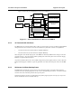

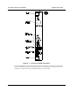

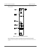

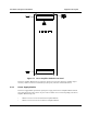

Table Of Contents

Installation and Operator Handbook Equipment Description
AMX–MA–00652 Issue 0.02 (USA)
7
Figure 2-4 shows the front panel controls, indicators and connectors and Table 2-2 lists the control and
indicator functions.
Figure 2-4 Controller Module Front Panel
There is a RESET switch, nine indicators and one RJ11 connector on the front panel of the Controller
Module. The RJ11 connector provides a standard RS 232 serial interface which allows maintenance
technicians to program and configure the module using the programmer and to monitor radio functions with a
computer.