
User Manual
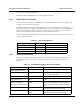
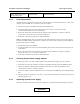
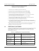
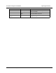

Table Of Contents

Installation and Operator Handbook Operating Instructions
AMX-MA-00654 Issue 0.02 (USA)
3
4. Switch on each Power Supply Module
Note that DC direct configurations have no power supplies or switches.
4.3.1 Initial Power-On Checklist
Refer to Table 4-2 to verify that power indications are correct. Should displays or indicators suggest a fault
condition, refer to 4.3.2 before proceeding.
The DRB-25 performs a self test and warm-up routine at power-on. During this, the Controller display
flashes while the Transceiver display remains blank. When the warm-up is complete, the Controller READY
indicator illuminates and the display changes to an oscillating pattern. The Transceiver then tunes to its
default channel and displays the channel number, and the unit is ready to operate.
At normal temperatures the Controller takes approximately one minute to warm up, however at -30°C warm-
up will take up to 10 minutes.
Table 4-2 Power-on Indicators
Equipment Indicator Normal Power On Indication
Power Supply Module ON Red lamp (in switch) lit
Controller Module 12 V PWR Green LED lit
Controller Module 7 V PWR Green LED lit
Transceiver Module PWR Green LED lit
4.3.2 Power-On Faultfinding
If the power-on indicators do not display normally, refer to Table 4-3 for simple faultfinding procedures.
Check each indication in sequence, proceeding to the next fault only when the previous one has been
eliminated.
Table 4-3 Faultfinding Chart for Power on Problems
Fault Probable Cause Recommended Action
Red Lamp in Power switch of
Power Supply Module not lit
Poor supply connection Check all connections to the relevant equipment.
Supply faulty Check supply for correct output of 115 V, 240 VAC
or 12 / 24 VDC as appropriate.
Power fuse blown Replace fuse as detailed below.
OUTPUT lamp on Power
Supply Module not lit
Power Supply Module
failure
Substitute known good Power Supply Module and
re-test.
7 V PWR and/or 12 V PWR
lamps on Controller or
Transceiver Module fail to light
System Power Supply
Failure
Check outputs of System Power Supply on
Backplane as detailed below. If either voltage is
absent, replace System Power Supply as detailed
below.
Controller Module Failure If Voltages are present, switch power off, substitute
known good Controller Module and re-test.
Transceiver Module
Failure
If Voltages are present, switch power off, substitute
known good Transceiver Module and re-test.