
User Manual
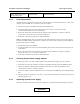
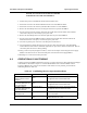

Table Of Contents

Installation and Operator Handbook Operating Instructions
AMX-MA-00654 Issue 0.02 (USA)
4
Controller or Transceiver
module display error code in
the range E01 to E99
User serviceable failure
or module failure.
See table B-1in Appendix B for likely cause and
recommended action
4.3.3 Fuse Replacement
AC DRB-25 units are protected by a single fuse located on the IEC connector/switch module. To check and if
required, replace the DRB-25 AC power fuse, proceed as follows:
1. Switch off all power to the DRB-25 and disconnect the Mains lead.
2. Unclip and withdraw the fuse slide immediately below the AC power connector on the IEC
connector/switch module on the rear of the cabinet.
3. Remove the fuse from the slide and check the continuity using a multimeter. If the fuse is ruptured,
replace with a new 205 size (20 x 5) 10 Amp cartridge fuse.
4. Fit the fuse to the slide and push the fuse slide firmly home.
DRB-25 units fitted with DC input are protected by fuses located adjacent to the DC power input connector.
Each Power Amplifier Module is protected by a separate fuse.To check and, if required, replace the DRB-25
DC power fuse, proceed as follows:
1. Switch off DC power to the DRB-25.
2. Unclip and withdraw the relevant fuse slide immediately below the DC power input connector on the rear
of the cabinet.
3. Remove the fuse from the slide and check the continuity using a multimeter. If the fuse is ruptured,
replace with a new ¼” x 1 ¼” 20 Amp cartridge fuse.
4. Fit the fuse to the slide and push the fuse slide firmly home.
4.3.4 Checking System Power Supply Outputs
To check the presence of 7 V and 12 VDC outputs from the System Power Supply, proceed as follows:
1. Disconnect and remove the Controller and Transceiver Modules from the front of the DRB-25 cabinet.
2. Observe the position of the backplane and identify the 12 VDC and 7 VDC test points between the
connectors for Transceiver 1 and the Controller
3. Connect the negative probe of a Multimeter to the 0 V test point or the DRB-25 system cabinet grounding
stud.
4. Using the positive lead, probe the +12 V and +7 V test points on the backplane card for the presence of the
indicated voltages
±
5%.
4.3.5 Replacing System Power Supply
If the above test indicates the lack of one or both voltage rails, replace the System Power Supply as follows:
WARNING