
User manual

WireS
p
eed Dual Connect Modem
User Guide
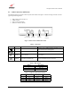
5.5 Cable Connectors and Pinouts
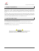
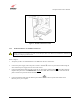
The following items are located on the rear panel of the modem. See Figure 1. Tables 2 through 5 list the connector
types and pinout designations.
• DSL (LINE) Connector (RJ-11)
• USB Connector
• Power Connector (Barrel)
• Ethernet Connector (RJ-45)
Power
Connector
USB
Connector
DSL
Line Connector
Ethernet
Connector
Figure 1. Dual Connect Modem Rear Panel
Table 2. Connectors
SYMBOL
N
AME
T
YPE
F
UNCTION
DSL 6-pin RJ-11 dual modular jack
Connects to an ADSL-equipped telephone jack or
DSL connection of a POTS splitter.
USB 4-pin USB Series B connector Connects the USB device to the PC.
∼
12V
Power Barrel connector Power source.
Ethernet 8-pin (RJ-45) modular jack Connects the Ethernet device to the PC.
Table 3. DSL Pinouts
Pinout Description
1, 2, 5, 6 Not Used
3 DSL Tip
4 DSL Ring
Table 4. USB Series B Connector Pinouts
Pin Name Description Cable Color
1 VBUS/Vcc 5 Vdc Red
2 D – Data – White
3 D + Data + Green
4 GND Ground Black
030-300196 Rev. A 5