f4t. o IiLD~' q OPERATORS MANUAL - . 7A·1 and 11A·1 MARINE DIESEL ENGINES PUBLICATION NO. 45145 1st Edition!April 2001 J WESTERBEKE CORPORATION· MYLES STANDISH INDUSTRIAL PARK 150 JOHN HANCOCK ROAD, TAUNTON, MA 02780-7319 U.S.A. TEL: (508)823-7677. FAX: (508)884-9688. WEBSITE: www.
OPERATORS MANUAL 7A·1 and 11A·1 MARINE DIESEL ENGINES PUBLICATION NO. 45145 15t Edition!April 2001 ~r~ 'WESTERBEKE ~ W£ST£RB£K£ CORPORATION· MYL£S STANDISH INDUSTRIAL PARK 150 JOHN HANCOCK ROAD, TAUNTON, MA 02780-7319 U.S.A. TEL: (508)823-7677· FAX: (508)884-9688· WEBSITE www.WESTERBEKECOM ~~~~ NHHA ~,.
CALIFORNIA PROPOSITION 65 WARNING Diesel engine exhaust and some of its constituents are known to the State of California to cause cancer, birth defects, and other reproductive harm. A WARNING Exhaust gasses contain Carbon Monoxide, an odorless and colorless gas. Carbon Monoxide is poisonous and can cause unconsciousness and death.
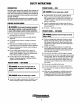
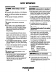
SAFETY INSTRUCTIONS INTRODUCTION PREVENT BURNS - FIRE Read these safety instructions carefuUy. Most accidents are caused by failure to follow fundamental rules and precautions. Know when dangerous conditions exist and take the necessary precautions to protect yourself, your personnel, and your machinery. The foUowing safety instructions are in compliance with the American Boat and Yacht Council (ABYC) standards. A WARNING: Fire can cause injury or death! • Prevent flash fires.
SAFETY INSTRUCTIONS ACCIDENTAL STARTING TOXIC EXHAUST GASES A WARNING: Accidental starling can cause injury A WARNING: Carbon monoxide (CO) is a deadly gas! or death! • Disconnect the battery cables before servicing the engine. Remove the negative lead first and reconnect it last. • Make certain all personnel are clear of the engine before starting. • Make certain all covers, guards, and hatches are re-installed before starting the engine.
SAFETY INSTRUCTIONS ABYC, NFPA AND USCG PUBLICATIONS FOR INSTAlliNG DIESEL ENGINES • Do not wear loose clothing or jewelty when servicing equipment; tie back long hair and avoid wearing loose jackets, shirts, sleeves, rings, necklaces or bracelets that could be caught in moving parts. • Make sure all attaching hardware is properly tightened. Keep protective shields and guards in their respective places at all times. • Do not check fluid levels while the engine is operating.
INSTALLATION When installing WESTERBEKE engines and generators, it is important that strict attention be paid to the following information: CODES AND REGULATIONS Federal regulations, ABYC guidelines and safety codes must be complied with when installing engines and generators in a marine environment.
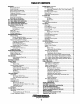
TABLE OF CONTENTS Introduction ................................................................................. 2 Cooling System (continued) Warranty Procedures ............................................................ 2 Product Software................................................................. 2 Notes, Caution and Warnings .............................................. 2 Model No.lSerial No. Location ........................................... 2 Component Locations ............................
INTRODUCTION This WESlERBEKE Diesel Engine is a product of WESlERBEKE'S many years of experience and advanced technology. We take great pride in the superior durability and dependable performance of our engines and generators. Thank you for selecting WESlERBEKE. This is the Operators Manual for the 7A-I and IIA-I Marine Diesel Engines. Most of the information in this manual applies to both models; where information applies to only one of the two models, the applicable model name will be indicated.
INTRODUCTION COMPONENT LOCATIONS SPARES AND ACCESSORIES Component locations in this manual are referenced from the front of the engine which is the end at which the raw water pump is located. Left and right sides are detennined as follows: imagine straddling the engine, facing the front of the engine: the left side is at your left, the right side is at your right. Certain spare parts will be needed to support and maintain your WESTERBEKE engine when cruising (see SUGGESTED SPARE PARTS KITS).
7A-1 DIESEL ENGINE SPECIFICATIONS ENGINE SPECIFICATIONS Engine Type LUBRICATION SYSTEM Diesel, four-cycle, one cylinder, raw water cooled, vertical, in-line overhead valve mechanism Lubrication System Forced lubrication by gear-driven pump Sump capacity 1.3 qts. (1.25 liters) Aspiration Naturally aspirated Govemor Mechanical, centrifugal type Operating Oil Pressu re (engine hot) 25.6-56.9 psi (1.8-4.0 kg/cm') Combustion System Direct injected Oil Grade Bore and Stroke 3.23 in. x 2.17 in.
7A-1 DIESEL ENGINE PARTS IDENTIFICATION AUTOMATIC DECOMPRESSION DEVICE HAN~-CRANK HANDLE GUIDE RAW WATER PUMP flEXIBLE MOUNTS RAW WATER INTAKE CONNECTION CYLINDER HEAD FUEL INJECTOR ---t--Hl'f-H,-#'4:;;;t,i~M"-:;5~~~~ WATER INJECTED EXHAUST MANIFOLDJELBOW FUEL INJECTION PUMP TRANSMISSION FUEL FILTER TRANSMISSION OUTPUT FLANGE Engines & Generators 5
11 A·1 DIESEL ENGINE SPECIFICATIONS ENGINE SPECIFICATIONS Engine Type LUBRICATION SYSTEM Diesel, four-cycle, one cylinder, raw water cooled, vertical, in-line overhead valve mechanism Aspiration Lubrication System Naturally aspirated Forced lubrication by gear-driven pump Sump Capacity 1.7 qts. (1.6 liter) 25.&-56.9 psi (1.8-4.0 kg/cm') Governor Mechanical, centrifugal type Operating Oil Pressure (engine hot) Combustion System Direct injected Oil Grade Bore and Stroke 3.74 in. x 2.91 in.
11A·1 DIESEL ENGINE PARTS IDENnFICATION CYLINDER HEAD fOAArpoc CIRCUIT BREAKER TlfROTrtE CONTROL STARTER FUEL INJECTOR COOlANT TE"'PERATURE SWITCH TIlANS""SSION OIPSTIClCIFlll FUEL FILTER 'TRANSMISSION
PREPARATIONS FOR INITIAL START-UP DIESEL FUEL PRE-START INSPECTION Use No.2 diesel fuel with a cetane rating of 45 or higher. Do not use kerosene or home heating fuel. Before starting your engine for the first time, or after a prolonged lay-up, check the following items: Care of the Fuel Supply D Check the engine oil level. The oil level must be between the max. and min. marks on the dipstick.
STARTING/STOPPING PROCEDURE ELECTRIC STARTING NOTE: The Automatic Decompression Device is not used for nOf77Ul1 electric starting. During engine operation, the pointer on this device is in the operating (9 o'clock) position. The 7A-I/llA-1 diesel engine has a 12 VDC electric starter. The engine is started by using a keyswitch on the control panel. The switch has three positions: OFF, ON and START. 1. Place the transmission in neutral and advance the throttle control to slightly open. 2.
STARTING/STOPPING PROCEDURE The upper illustration shows the distance [4.5 in. (115 mm)] that the standard hand-crank handle protrudes from the crank-handle guide on the engine. An additional 2.5 in. (64 mm) minimum must be allowed for room to insert the handle. HEX-HEAD BOLT If hand cranking must be done from outside the engine compartment (see lower illustration), then the standard hand-crank handle must be extended to the required length. This modification to the handle must be done by the owner.
STARTING/STOPPING PROCEDURE Manual Starting Procedure To manually start the engine, follow the procedure described below. When starting after cold nights or freezing temperatures when the engine must first be turned over with no compression, follow all of the steps, beginning with Step 1. If cold weather is not a factor, bypass Steps 1-3, and begin with Step 4. 4. Crank the engine counterclockwise approximately 10 to 20 times until the engine turns freely. Then remove the crank handle. S.
STARTING/STOPPING PROCEDURE Initial Start-Up Check List o o POINTER IN THE OPERATING POSITION o o Check for possible leaks from all the connections. Make sure the cooling water is discharging properly, outboard from the exhaust outlet. Make certain that the engine is mounted securely. Listen for unusual sounds and vibrations. STOPPING THE ENGINE 9. If the engine has not started, repeat Steps 5-9 above, and consider cranking at a higher speed.
ENGINE BREAK-IN PROCEDURE ENGINE BREAK-IN PROCEDURE Although your engine has experienced a minimum of one hour of test operations at the factory to make sure accurate assembly procedures were followed and that the engine operated properly, a break-in time is required. The service life of your engine is dependent upon how the engine is operated and serviced during its initial 50 hours of use. 4. Avoid rapid acceleration, especially with a cold engine. S. Use caution not to overload the engine.
MAINTENANCE SCHEDULE In order to use this Maintenance Schedule, it will be necessary A WARNING: Never attempt to perfonn any service log your engine hours. Use your engine hounneter or record your engine hours by running time. NOTE: Many of the following maintenance procedures are simple but others are more difficult and may require the expert /awwledge of a service mechanic. to while the engine is running.
MAINTENANCE SCHEDULE MAINTENANCE FREQUENCY COMPONENT AFTER FIRST 50 HOURS DAILY DR EVERY 8 HOURS WEEKLY EVERY 100 HOURS EVERY 300 HOURS EVERY 600 HOURS • • Adjust to 1000 - 1200 rpm. • • • Visual inspection Cleaning the engine Lubricate control panel keyswitch Retorque the nuts (see TIGHTENING THE CYLINDER HEAD under ENGINE ADJUSTMENTS). Initial fluid change at 25 hours, then every 300 hours or at winterizing.
EXHAUST SYSTEM DESCRIPTION EXHAUST SYSTEM PRECAUTIONS It is important to install a proper exhaust system to avoid engine flooding. The system must be designed to prevent water from Carbon Monoxide entering the exhaust line under any sea conditions and at any angle of the vessel's hull. Exhaust system failures are not covered by Westerbeke's warranty. The installer should have a basic knowledge of marine installation requirements.
EXHAUST SYSTEM Carbon Monoxide Detectors It is extremely important that a carbon monoxide detector(s) be installed in your boat's living and/or sleeping quarters. Make sure it is manufactured for the marine industry. They are inexpensive and available at your marine supplier. Insulation Inspect insulated portions of the exhaust system to ensure there is no deterioration of the insulation.
LUBRICATION SYSTEM DESCRIPTION The lubricating system is a pressure feeding system using an oil pump. The engine oil is drawn from the oil sump by the oil pump, which drives the oil, under pressure, through the various lubricating points in the engine. The oil then returns to the oil sump to repeat the continuous cycle. The gear-driven oil pump is built into the oil sump. The oil is pumped through a spin-on type oil filter (Model IIA-I only) to the main bearing and connecting rod bearing.
LUBRICATION SYSTEM CHANGING THE OIL Change the oil after an initial 50 hours of break-in operation and every 100 hours of operation thereafter. Change the oil only when the engine is warm. ~,l«
LUBRICATION SYSTEM Adding the New 011 1. Add the new oil through the oil fill. 2. Replace the oil filler cap. When tightening it, do not use too much force otherwise the plastic plug may break. 3. After refilling with new oil, run the engine for a few moments. Make sure there is no leakage around the oil filler cap or the new oil filter (ModelllA-l only), then stop the engine. Then check the quantity of oil with the lube oil dipstick.
COOLING SYSTEM RAW WATER COOLING SYSTEM The engine is designed for direct raw water cooling. The engine operates with a raw water coolant temperature up to 90" F (32° C). The raw water flow is created by a positive displacement impeller pump that is gear-driven by the camshaft. This pump draws cooling water directly from the raw water source (ocean. lake or river) through a hose. The raw water is pumped through a tee which splits the flow.
COOLING SYSTEM RAW WATER PUMP RAW WATER INTAKE The raw water pump is a self-priming, rotary pump with a non-ferrous housing and a neoprene impeller. The impeller has flexible vanes which wipe against a curved cam plate within the impeller housing, producing the pumping action. On no account should this pump be run dry as water acts as a lubricant for the impeller. There should always be a spare impeller and impeller cover gasket (an impeller kit) onboard.
COOLING SYSTEM HOSE FROM THE SIPHON-BREAK RAW WATER INTAKE STRAINER OWNER INSTALLED (TYPICAL) HOSE TO THE SIPHON-BREAK THERMOSTAT HOUSING SIPHON-BREAK For installations where the water-injected exhaust elbow is close to or below the vessel's waterline, provisions must be made to install a siphon-break in the raw water supply hose to the exhaust elbow.
AIR INTAKE FILTER DESCRIPTION The 7A-I and llA-l marine diesel engines, when operating in the cruise rpm range, will typically consume in excess of 1000 cubic feet of air per hour. The engine compartment must be well ventilated, and the air flow into the engine must be unrestricted. Air Filter The air fliter cartridge prevents dust and dirt from entering the engine; it also improves oil consumption, extends engine life, and quiets the engine.
FUEL SYSTEM DIESEL FUEL FUEL FILTER Use No.2 diesel fuel with a cetane rating of 45 or higher. Do not use kerosene or home heating fuel. The frequency of a fuel filter change depends on the degree of contamination of the fuel, however it should be performed at least after every 100 hours of engine operation. FUEL ADDITIVES If fungus or bacteria is causing fuel problems, you should have an authorized dealer correct these problems.
FUEL SYSTEM FUEL LINES FUEL INJECTION PUMP The fuel return line at the fuel tank should extend down to the bottom of the tank in the same manner as the fuel pickup tube. This must be done in an installation where the fuel tank is located below the engine's fuel system. This precaution insures against hard starting due to air displacing fuel siphoning out of the engine's fuel system through the return line when the engine is shutdown.
DC ELECTRICAL SYSTEM 12 VOLT DC CONTROL CIRCUIT ENGINE CIRCUIT BREAKER The engine has a 12 volt DC electrical control circuit that is shown on the wiring diagrams. Refer to these diagrams when troubleshooting or when servicing the DC electrical system. The DC wiring harness on the engine is protected by an enginemounted manual reset circuit breaker (10 amps DC). Excessive current draw or electrical overload anywhere in the instrument panel wiring or engine wiring will cause the breaker to trip.
DC ELECTRICAL SYSTEM ALTERNATOR TROUBLESHOOTING MULTIMETER A WARNING: A failed alternator can become very hot. Do not touch until the alternator has cooled down. Use this troubleshooting section to determine if a problem exists with the charging circuit or with the'alternator. If it is determined that the alternator or voltage regulator is faulty, have a qualified technician check it. The alternator charging circuit charges the starting battery and the service battery.
DC ELECTRICAL SYSTEM Checking the Service Battery 7. Now check the voltage between the alternator output terminal (B+) and ground. If the circuit is good, the voltage at the alternator will be the same as the battery, or if an isolator is in the circuit the alternator voltage will be zero. If neither of the above is true, a problem exists in the circuit between the alternator and the battery. Check all the connections - look for an opening in the charging circuit. Check the voltage of the service battery.
DC ELECTRICAL SYSTEM' 7A-1 MARINE DIESEL ENGINE WIRING DIAGRAM #45593 I' 4 Bl K RD tI4R[O r-------------, I WATER TEIF. SWITCH :r~ l§j SEE NOTE 2 I I I + I IlL PRESSUIE SWITCH o r_- - - - - - - -, ~ w ~ : I I I 5 CfICUT IIIIEAKER 4 '!WE IlEl..AY RELAY 3 110 RED .,4 RED GLOW PLUOS STARlBI I'IEt£AT SOI..ENOIl I' 4 V 10 • I 2 WHT '12 RED 11.4 VEL i:14 ORANGE 51 • I 4 Bl II.
DC ELECTRICAL SYSTEM 7A-1 MARINE DIESEL ENGINE WIRING SCHEMATIC #45593 G) < ) 12 VDC G STARTER r----' STARTER SOLENOIO _____ J GlOWPLUGS r----' I PREt£AT I I SOLENOID I I I - - - - _ .. 30 ~8~7 AlTERNATOR ______~________~____________________________~__/ 86 ( ClRCUT BREAKER NO 5 T1r.tE DEl..AY RELAY WATER TEMP. SWITCH 3 NC OIl PRESSURE SWITCH SI 6 7 5 3 PI AlARM HOl.
DC ELECTRICAL SYSTEM 11A-1 MARINE DIESEL ENGINE WIRING DIAGRAM # 44542 • I 4 BL K r------------..., I I I 1"0"" SEENlTE2:~ I~ .J I I I + I WATER TEJoP. SlilTCH : IlL PIESSUAE SWITCH r.- - - - - - - ..., ~ ® STARTER ® 114 VIO 114 RED/WHT ®112 WHT ®1I2RED .14 y[ l 51 II. BLK PI .:;: ;; .'".- KEY SWITCH L REMOTE PAt£l.
DC ELECTRICAL SYSTEM 11A-1 MARINE DIESEL ENGINE WIRING SCHEMATIC # 44542 + ~(-----------12 vee ----------~) STARTER STARTER SOLENOID ALTERNATOR ( CIRCUT BREAKER WATER TEMP. SWITCH NC DI.. PRE5SUE SWITCH SI B 5 7 3 P1 ALARM HOUR METER + START KEY SWITCH NOTES: I. THIS PRODUCT IS PROTECTED BY A MANUAL RESET CIRCUIT BREAKER LOCATED NEAR THE STARTER. EXCESSIVE CURRENT WILL CAUSE THE BREAKER TO TRIP AND THE ENGINE WILL SHUT DOWN. THE BUILDER/OWNER MUST BE SURE THAT THE INSTRUMENT PANEL.
GLOW PLUGS MODEL 7A-1 ONLY DESCRIPTION The glow plugs (2) are wired through the preheat solenoid. When PREHEAT is pressed at the control panel this solenoid should "click" on and the glow plug should begin to get hot. Re-install the plugs in the air intake adapter and test them again. __ The plugs should get very hot (at the terminal end) within 7 to 15 seconds. If the plugs don't heat up quickly, check for a short circuit. When reinstalling the glow plugs, use anti-seize compound on the threads.
ENGINE ADJUSTMENTS NOTE: WESTERBEKE recommends that the following engine adjustments be performed by a competent engine mechanic. The information below is provided to assist the mechanic. TIGHTENING THE CYLINDER HEAD After the initial break-in period (approximately 50 hours), retorque the cylinder head nuts. Do this when the engine is cold. 1. Remove the cylinder head cover and gasket. 2. Retighten the four cylinder head nuts in an X-pattern sequence as shown in the illustration. Start with any nut.
ENGINE ADJUSTMENTS NOTE: WESTERBEKE recommends that the following engine adjustments be performed by a competent engine mechanic. The information below is provided to assist the mechanic. TESTING THE FUEL INJECTOR Checking The Injection Starting Pressure NOTE: The fuel injector must be serviced in a clean room environment. 1. Set the nozzle tester in a clean place where there is no dust or dirt. Removing the Fuel Injector 2. Mount the nozzle and the nozzle holder on the nozzle tester. 1.
ENGINE ADJUSTMENTS NOTE: WESTERBEKE recommends that the following engine adjustments be peiformed by a competent engine mechanic. The information below is provided to assist the mechanic. Tightness of the Valve Seat Checking the Nozzle Body and Needle Valve Apply a pressure of 2600 Iblin2(182 kglcm2) and check if fuel leaks from the injection nozzle holes. If fuel leaks, disassemble, wash and recheck the injector nozzle or replace it 1.
ENGINE ADJUSTMENTS NOTE: WESfERBEKE recommends that the following engine adjustments be performed by a competent engine mechanic. The infonnation below is provided to assist the mechanic. DRIVE BELT ADJUSTMENT The drive belt must be properly tensioned. A loose drive belt will not provide proper alternator charging and will eventually damage the a1temator. A drive belt that is too tight will pull the alternator out of alignment and/or cause the alternator to wear out prematurely.
ENGINE TROUBLESHOOTING The following troubleshooting chart provides information based upon certain problem indicators, the probable causes of these problems, and the recommendations to overcome them. 1. Engine will not start Problem Fuel supply failure (check by cranking engine and listening for the characteristic squirting in the fuel injector). Poor compression Difficult to crank the engine Probable Cause Remedy If squirting cannot be heard: No fuel in tank. Vent hole in tank cap plugged.
ENGINE TROUBLESHOOTING 3. Engine lacks power and/or makes black smoke Problem Remedy Probable Cause 1. Engine overloaded. 2. Power reduction due to altitude and/or ambient temperature has not been considered. 3. Clogged air filter. 1. Reduce the load. 1. Gasket under injector missing or too many gaskets are installed. 2. Fuel filter clogged. 3. Faulty injection nozzle. 4. Faulty injection pump. 1. Correct the number of gaskets. 1. Excessive carbon on piston and cylinder head. 2. Faulty piston rings.
ENGINE TROUBLESHOOTING Problem Probable Cause Remedy Blue smoke 1. 2. 3. 4. Breather valve is clogged. Oil seal at intake valve is defective. Worn valves/valve guides. Worn piston/cylinder. White smoke 1. Fuel timing is too late. 2. Injector nozzle is worn out. 3. Low engine operating temperature. 1. Adjust timing. 2. Replace nozzle. 3. Clean thermostat. Oil in exhaust discharge 1. Rings not seated. 2. Low compression - bad valve. 1. Initial 50 hours of operation required to seat rings. 2.
HURTH HBW TRANSMISSION WESTERBEKE'S 7A-l and llA-l diesel engines each use a HURTH Model HBW 40 transmission. Installation, operation, maintenance and troubleshooting infonnation for this transmission is included in the following instructions. The control cable, or rod, should be arranged at a right angle to _ the actuating lever when in the neutral position. The neutral position of the shift lever on the control console should coincide with the neutral position of the actuating lever.
HURTH HBW TRANSMISSION INITIAL OPERATION LOCKING THE PROPELLER All HBW maine transmissions are test-run on a test stand with the engine at the factory prior to delivery. For safety reasons the fluid is drained before shipment. Fill the gearbox with Automatic Transmission fluid (DEXTRON 111). The fluid level should be up to the index mark on the dipstick. To check the fluid level, just insert the dipstick, do not screw it in. Screw the dipstick into the case after the fluid level is checked, and tighten.
HURTH HBW TRANSMISSION MAINTENANCE Transmission maintenance is minimal. Keep the exterior housing clean, check the fluid level as part of your regular routine, and change the fluid every 300 operating hOUTS. Periodically inspect the transmission for leaks and corrosion. Lubricate the cable connections. Lay-up/Winterize Storage requires special care. Follow these procedures. o Clean up the transmission and touch up unpainted areas (use heat resistant paint).
HURTH HBW TRANSMISSION TROUBLESHOOTING CONTROL CABLES A new cable and perhaps a new linkage mechanism may be needed. While the cable is loose, shift the transmission in and out of gear using the actuating lever on the side of the transmission to make sure there's no binding inside the case. The majority of transmission difficulties arise as a result of problems with control cables rather than from problems with the transmission itself.
LAY-UP AND RECOMMISSIONING GENERAL Many owners rely on their boatyards to prepare their craft, including engines and generators, for lay-up during the off season or for long periods of inactivity. Others prefer to accomplish lay-up preparation themselves. The procedures which follow will allow you to perfonn your own lay-up and recommissioning, or you may use them as a check list if others do the procedures.
LAY-UP AND RECOMMISSIONING STARTER MOTOR STORAGE Lubrication and cleaning of the starter drive pinion is advisable. Make sure the battery connections are shut off before attempting to remove the starter. Take care in properly replacing any electrical connections removed from the starter. Thoroughly clean the outside of the engine, then store the engine in a dry place, protected against the weather.
7A·1 & 11 A·1 TORQUE SPECIFICATIONS Component MOOEl7A-1 SPANNER SIZE (mm) - MODEL 11A-1 MIN. MAX. SPANNER SIZE (mm) TIGHTENING TORQUE (Nm) TIGHTENING TORQUE (Nm) MIN. MAX.
STANDARD HARDWARE BOLT HEAD MARKINGS Metric bolt class numbers identify bolts by their strength with 10.9 the strongest 1. Use the torque values listed below when specific torque values are not available. 2. These torques are based on clean, dry threads. Reduce torque by 10% when engine oil is used. 3. Reduce torques by 30% or more, when threading capscrews into aluminum.
METRIC CONVERSIONS INCHES TO MILUMETERS mm Inches 1 2 3 4 5 10 25.40 50.80 76.20 101.60 127.00 254.00 15 20 25 30 35 40 MILUMETERS TO INCHES mm Inches 381.00 508.00 635.00 762.00 889.00 1016.00 mm Inches mm Inches 1 2 3 4 5 10 0.0394 0.0787 0.1181 0.1575 0.1969 0.3937 15 20 25 30 35 40 0.5906 0.7874 0.9843 1.1811 1.3780 1.5748 = = 10 MILLIMETERS 1 CENTIMETER, 100 CENTIMETERS 1 METER INCHES TO METERS Inches Meters 1 2 3 4 5 6 0.0254 0.0508 0.0762 0.1016 0.1270 0.
STANDARD AND METRIC CONVERSION DATA LENGTH-DISTANCE Inches (in) x 25.4 = Millimeters (mm) x .0394 = Inches Feet (ft) x .305 = Meters (m) x 3.281 = Feet Miles x 1.609 = Kilometers (km) x .0621 =Miles VOLUME Cubic Inches (in3) x 16.387 = Cubic Centim~ters x .061 =in3 Imperial Pints (IMP pt) x .568 = liters (L) x 1.76 = IMP pt Imperial Quarts (IMP qt) x 1.137 =liters (L) x.88 = IMP qt Imperial Gallons (IMP gal) x 4.546 = liters (L) x .22 = IMP gal Imperial Quarts (IMP qt) x 1.201 = US Quarts (US qt) x .
SUGGESTED SPARE PARTS KITS Carry only Genuine WESTERBEKE Spare Parts SPARE PARTS KITS WESTERBEKE offers two Spare Parts Kits, each packaged in a rugged hinged toolbox. Kit "A" includes the basic spares. Kit "B" is for more extensive off-shore cruising.
Engines & Generators 1045-.