
Installation manual


ADMIRAL
CONTROL
PANEL
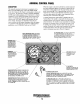
DESCRIPTION
This manually-operated control panel is equipped with a
KEY switch and RPM gauge with an ELAPSED
TIME
meter which measures the engine's running time
in
hours and
in
III 0 hours. The panel also includes a WATER TEMPER-
ATURE gauge which indicates water temperature in degrees
Fahrenheit, an
OIL PRESSURE gauge which measures the
engine's oil pressure
in
pounds
per
square inch, and a DC
control circuit VOLTAGE gauge which measures the
sys-
tem's voltage. All gauges are illuminated when the key
switch is turned on and remain illuminated while the engine
is
in
operation. The panel also contains two rubber-booted
pushbuttons, one for PREHEAT and
on,?
for START.
RPM
GAUGE:
REGIS-
TERS
REVOLUTIONS
PER
MINUTE
OF
THE
ENGINE
AND
CAN
BE
RECALIBRATED
FOR
ACCURACY
FROM
THE
REAR
OF
THE
PANEL.
HOURMETER:
REGISTERS
ELAPSED
TIME,
AND
SHOULD
BE
USED
AS
A
GUIDE
FOR
THE
MAINTENANCE
SCHEDULE.
WATER
TEMPERATURE
GAUGE:
THIS
GAUGE
IS
GRADUATED
IN
DEGREES
FAHRENHEIT
AND
IS
ILLUMINATED
WHILE
THE
KEY
SWITCH
IS
TURNED
ON.
THE
ENGINE'S
NORMAL
OPERATING
TEMPERATURE
IS
170·
-190· F (n· -
SS·C).
PREHEAT
PRESSED,
ENERGIZES
THE
When the engine is shut down with the key switch turned
off,
the water temperature gauge will continue to register the last
temperature reading indicated
by
the gauge before electrical
power was turned
off
The oil pressure gauge will fall to zero
when the key switch is turned
off
The temperature gauge
will once again register the engine's true temperature when
electrical power is restored to the gauge.
A separate alarm buzzer with harness is supplied with every
Admiral Panel. The installer
is
responsible for electrically con-
necting the buzzer to the four-pin connection on the engine's
electrical harness. The installer
is
also responsib,le for installing
the buzzer
in
a location where
it
will
be
dry and where
it
will
be audible to the operator should
it
sound while the engine
is
running. The buzzer will sound when the ignition
key
is
turned
on and should silence when the engine has started and the
engine's oil pressure rises above
15
psi
(1.1
kg/cm2).
,
OIL
PRESSURE
GAUGE:
THIS
GAUGE
IS
GRADUATED
IN
POUNDS
PER
SQUARE
INCH
(PSI)
AND
IS
ILLUMINATED
WHILE
THE
KEY
SWITCH
IS
TURNED
ON.
THE
ENGINE'S
NORMAL
OPERATING
OIL
PRESSURE
RANGES
BETWEEN
40
-
85
pSi.
SWITCH:
PROVIDES
POWER
ONLY
TO
THE
INSTRUMENT
PANEL
CLUSTER.
DC
VOLTMETER:
INDICATES
THE
AMOUNT
THE
BATTERY
IS
BEING
CHARGED.
SHOULb
SHOW
13V
TO
14V.
AUTOMATIC
ALARM
SYSTEM
ALTERNATOR'S
EXCITER,
THE
FUEL
LIFT
PUMP,
THE
FUEL
SOLENOID
ON
THE
INJECTION
PUMP,
AND
THE
ENGINE'S
GLOW
PLUGS.
IT
BYPASSES
THE
ENGINE'S
OIL
PRESSURE
ALARM
SWITCH.
IN
ADDITION,
THIS
BUTTON
ENERGIZES
THE
START
BUTTON.
I/<'
:
SUPPLIED
WITH
THE
INSTRUMENT
PANEL.
IF
THE
ENGINE'S
COOLANT
~...:
REACHES
210·
F
(99·C),
THIS
SWITCH
WILL
CLOSE
SOUNDING
THE
START
BUTTON:
WHEN
PRESSED,
ENERGIZES
THE
STARTER'S
SOLENOID
WHICH
CRANKS
THE
ENGINE.
THIS
BUTTON
WILL
NOT
OPERATE
ELECTRICALLY
UNLESS
THE
PREHEAT
BUTTON
IS
PRESSED
AND
HELD
AT
THE
SAME
TIME.
---
ALARM
WHICH
WILL
EMIT
A
CONTINUOUS
SIGNAL.
OIL
PRESSURE
ALARM:
AN
OIL
PRESSURE
ALARM
SWITCH
IS
LOCATED
OFF
THE
ENGINE'S
OIL
GALLERY.
THIS
SWITCH
MONITORS
THE
ENGINE'S
OIL
PRESSURE.
SHOULD
THE
ENGINE'S
OIL
PRESSURE
FALL
TO
5
-10
psi
(0.4
-
0.7
kg/em'),
THE
SWITCH
WILL
CLOSE
SOUND-
ING
THE
ALARM.
IN
THIS
EVENT,
THE
ALARM
WILL
EMIT
A
PULSATING
SIGNAL.
Engines & Generators
5