
Installation manual


ELECTRONIC
GOVERNOR
ELECTRONIC
GOVERNING
SYSTEM
The system is composed
of
three basic components:
1. Controller -
Mounted
inside the
instrument
panel box.
2. Sensor
~
Installed on the generator stator housing over the
flywheel ring gear.
3.
Actuator - Mounted at the front
of
the engine and
attached with linkage to the throttle arm of the injection
pump.
Controller
Adjustments
1.
Speed. - This adjustment is used
to
raise or lower engine
speed
to
the desired hertz.
2. Gain -
This
adjustment
affects the reaction lime
of
the
actuator
to the
generator/engine
load
changes.
NOTE:
A high Rajn
adjustment
can
induce
an
oscillating
of
the actuator producing a hunting mode. In such cases, lessen
the gait! adjustment.
Calibration
1.
With no power to
the
governor
(engine
not running)
adjust the GAIN potentiometer to
9:00
o'clock.
•
•
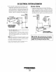
SENSOR
PV
#039172
, I L '
12
VDC
SUPPLY
SPEED",n
GAIN
i\.J
CONTROLLER
PN
#303008
•
2. Start the
engine
and
adjust
the
speed
hy turning the
SPEED
potentiometer
clockwise to desired speed.
ELECTRONIC
GOVERNOR
TERMINAL
NOTE:
COlIlrol/ers are fact01Y adjusled
La
minimum rpm.
Howeper, j()r
safet}!,
Olle
should
he
capable
ufdisahling
the
£!ugill£!
ifan
(wer::.peed
should
exist.
3.
At no load, turn the
GAIN
potentiometer
clockwise
until
the
engine
hegins
to
hunt. If
the
engine
does
not hunt,
physically upset the
governor
linkage.
4.
Turn the gain
potentiometer
counterclockwise
until the
engine
runs stahle.
FLYWHEEL
HOUSING
/'
/~
BACK
PLATE
TO
ELECTRONIC
CONTROLLER
-..v
WESTERBEKE
Engines & Generators
26
LINEAR
ACTUATOR
KEEP
ACTUATOR
LINKAGE
WELL
LUBRICATED
G?'~~!!'-'"
LINEAR
ACTUATOR
(20
KW
SHOWN)