
Installation manual


ENGINE
ADJUSTMENTS
NOTE:
WESTERBEKE recommends that the following engine adjust-
ments be performed by a competent engine mechanic.
The
information
below is provided to assist the mechanic.
VALVE
CLEARANCE
ADJUSTMENT
NOTE:
Retorque the cylinder
head
bolts hefore adjusting the
engine:, valves. See
TORQUING
THE
CYLINDER HEAD
BOLTS.
A
CAUTION:
Adjust
the
valve
clearance
when
the
engine
is
cold.
Valves
are
adjusted
by
cylinder
in
the
firing
order
of
the
engine.
Tighten
the
cylinder
head
bolts
to
the
specified
torque
before
adjusting
the
valves.
Pull
off
the air breather pipe from the rocker cover, and take
off the rocker cover bolts and the rocker cover to expose the
rocker shaft and valve assembly.
Position the
No.1
piston
at
Top Dead Center
(TDC)
on its
compression stroke and adjust the #
1,
2,
3 and 6 valves as
illustrated.
Position the
No.4
piston
at
IDe
of
its compression stroke
and adjust the
# 4, 5, 7 and 8 valves. The valves are num-
bered 1 to 8 from the front
of
the engine to the back.
Adjust each valve's clearance by inserting a
0.012 inch (0.3
mm) fecler gauge between the rocker arm and the valve
stem. Make sure to adjust
all valves to
O'()12
inches (0.3 mm)
while the engine
is
cold.
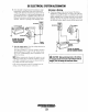
VALVE
ADJUSTMENT
SEQUENCE
WHEN
NO.4
CYLINDER
IS
AT
TOP
DEAD
CENTER
• •
3
,
4
EXH~UST
I
4
INTAKE
I 2
EX~AUST
3IN~AKE
2
INTAKE
1
INTAKE
3
EXHAUST
I
3
11
EXH~UST
I
, ,
WHEN
NO.1
CYLINDER
IS
AT
TOP
DEAD
CENTER
VALVE
CLEARANCE
=,*=0.01'"'
(0.3
MM)
COLO
ENGINE
DRIVE
BELT
ADJUSTMENT
For your safety, Westerbeke generator models come equipped
with
belt guards that cover over the belt(s) on the front
of
the
engine.
("Out
of
sight - oul
of
mind:'
The belt guard
is
NOT
installed
lelf
that purpose.) Operators are advised that proper
inspection, service, and maintenance
is
required.
Drive belts must be properly tensioned. Loose drive
belts
will
not provide proper alternator charging and will eventu-
ally damage the alternator. Drive
belts that are too tight will
pull the
alternator out of alignment and/or cause the alterna-
tor to wear out prematurely. Excessive drive belt tension can
also cause rapid wear of the belt and reduce the service life
of
the fresh water pump's bearing. A slack belt or the pres-
ence
of
oil
on
the belt can cause belt slipping, resulting
in
high operating temperatures.
The drive
belt
is
properly adjusted if the belt can he deflected
no
less than 3/8 inch (IOmm) and
no
more than 1/2 inch
(12mm) as the
belt
is
depressed with the thumb at the mid-
point between the two pulleys on the longest span
of
the belt.
A spare belt or belts should always
be
carried on board.
A
WARNING:
Never
attempt
to
check
or
adjust
the
drive
belt's
tension
while
the
engine
is
in
operation.
Adjusting
Belt
Tension
1.
Remove the belt guard.
2. Loosen the alternator adjusting strap bolt and the base
mounting bolt.
3. With the belt loose, inspect for wear, cracks, and frayed
edges.
4.
Pivot the alternator
on
the base mounting bolt to the left
or right as required,
to
loosen or tighten.
S.
Tighten the base mounting bolt and the adjusting strap
bolt.
6. Operate the generator for about 5 minutes then shut down
and recheck the belt tension.
7.
Replace the guard.
3/8"
TO
1/2"
DEFLECTION
Engines & Generators
28