
Installation manual


ENGINE
ADJUSTMENTS
TORQUING
CYLINDER
HEAD
BOLTS
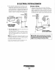
Tighten the cylinder head bolts according to the sequence
shown
in the illustration below.
Make
sure the engine
is
cold
when this is done, and loosen
one
head bolt
one-half
turn and
then righten
it
between 85 to
90
Ib-f!. (11.8 to 12.5 kg/m) for
the
BED
20KW
and
25KW.
The 32
KW head bolts do NOT
require retorquing.
CYLINDER
HEAD
BOLT
PATTERN
14
'i
2 3
'1
15
-16
5
4
ENGINE
COMPRESSION
Check
the compression pressure. To
do
this,
warm
the
engine,
remove
all fuel injectors,
or
glow
plugs, disconnect
the
fue! shut-off solenoid wire, and install a compression
adapter
in
the injector hole
or
glow plug hole. Connect a
compression tester on the adapter and crank the engine with
the starter motor until the pressure reaches a maximum value.
Repeat this process for each cylinder. Look for cylinders with
dramatically (at
least 20%) lower
compression
than the
aver~
age
of
the others. Compression pressure
should
not differ by
more than
42.7 psi (3.0 kg/cm2) at 200 rpm.
COMPRESSION
TESTER
ADAPTER~
I","~~,.r((
_
t:t5iI["'
______
INJECTOR
OR
GLOW
----------
Of
i--
PLUG
HOLE
If a weak cylinder
is
flanked by healthy cylinders, the prob-
lem
is
either valve-or piston related.
Check
the valve clear-
ances for the weak cylinder, adjust as needed
and
test again.
If
the cylinder
is
still low apply a small
amount
of
oil into'the
cylinder to seal the rings and repeat the test.
If compression
comes
up - the rings arc faulty.
Abnonnally
high readings on all cylinders indicate heavy
carbon accumulations, a condition that might be accompa-
nied by high pressures
and
noise.
NOTE:
In case
of
severe vibrations and detonation noise, have
the injectors checked and overhauled by an authorized fuel
injection service celller. Poor
fuel quality, cOlllaminates
and
loss
of
positive fuel pressure to the injection
pump
will result
in
injector faults.
When re-installing the glow plugs use anti-seize
compound.
TESTING
FUEL
INJECTORS
Remove and check fuel injectors.
The
injector spray pressure
should be 1920
±71
psi (135
kg/cm'
±
10
kg/cm').
TESTER
INJECTION
PRESSURE
TEST
1.
Using the nozzle tester, check the spray pattern and
injection starting pressure
of
nozzle and, if
it
exceeds the
limit, adjust
or
replace the nozzle.
When
using nozzle
tester, take the following precautions:
A
CAUTION:
The
spray
injected
from
the
nozzle
is
of
such
velocity
that
it
may
penetrate
deeply
into
the
skin
of
fingers
and
hands,
destroying
tissue.
If
it
enters
the
bloodstream,
it
may
cause
blood
poisoning.
a.
If the diesel fuel
of
the nozzle tester is stained, replace
it.
At the
same
time, clean or replace the fuel filter.
h.
Set the nozzle tester in a clean place where there
is
no
dust
or
dirt.
e. Mount the nozzle and nozzle holder
on
the nozzle
tester.
d.
Operate the hand lever
of
nozzle tester several times to
bleed the air in the nozzle line, then move the hand
lever at intervals
of
one
stroke
per
second while read-
ing the injection starting pressure.
Start
to
injection: 135 -
140
kg/cm2 (1920-1990 Ib/in2)
ADJUSTING
SHIM
I
SHIM
THICKNESS
~j
I
INJECTOR
O.lmm
O.2mm
O.3mm
O.5mm
"tIY'
WESTERBEKE
Engines
&
Generators
29