
Installation manual


ENGINE
ADJUSTMENTS
If the
pressure
is
different from the standard value, adjust
to
the specified pressure by increasing
or
decreasing the thick-
ness
of
the adjusting shim.
The shim has 10 different thicknesses for every 0.05 mm
(0.0020 in) [rom 1.0
mm
(0.0393 in) to 1.95
mm
(0.0768 in).
As
0.05
mm
(0.0020 in)
is
increased, approx. 5.0 kg/em'
(7
J.1
Iblin
2
)
of
injection pressure increases.
When
replacing
the shim, grip the retaining nut
in
a vise and
remove
the
body with a wrench. Tighten the retaining nut
to
the specified torque.
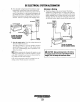
INSPECTING
THE
SPRAY
PATTERN
1.
Operate
the hand lever
of
the nozzle tester at intervals
of
one
stroke
per second to check
if
the fuel is injected cor-
rectly in its axial direction. A nozzle
is
defective
if
it
injects fuel
in
an oblique direction or
in
several separate
strips. Also, a spray
in
the fonn
of
particles indicates a
defect.
These
defects may sometimes be caused by clog-
ging
with dust and, therefore, all parts should be carefully
cleaned before reassembly. (Care should be taken
not
to
expose
one's
skin to this spray as
it
may penetrate the
skin
and
cause infection.)
NORMAL
FAUlTY
ANGLE
FAULTY
DIRECTION
CHATTERING
TEST
2. Apply the
pressure
of
115 kg/cm' (1635 Ib/in') to nozzle
by operating
the
hand lever, and check the drips from the
nozzle tip. If it
drips
or
ha<>
a large accumulation
of
fuel
on the bottom,
it
is considered defective and should be
replaced. A very small amount
of
fuel may sometimes
remain on
the
tip
of
the nozzle; however, this does not
indicate a defect.
•
CORRECT
WRONG
AFTER
DRIP
TEST
Engines & Generators
30