
Installation manual


THE
BE
GENERATOR
SINGLE
AND
THREE
PHASE
DESCRIPTION
This
generator
is a four-pole, brush less, self-excited genera-
tor which requires only the driving force
of
the engine
to
pro-
duce
AC
output.
The
copper
and laminated iron
in
the exciter
stator are responsible for the self-exciting feature
of
this gen-
erator.
The
magnetic
field produced causes an
AC
voltage to
be induced into the related excitor rotor windings during
rotation.
Diodes
located in the exciter rotor rectify this volt-
age
to
DC;:
and
supply
it
to the windings
of
the rotating field.
This
creates
an electromagnetic field which rotates through
the
windings
of
the main stator, inducing an
AC
voltage
which
is
supplied
to a load.
An
AC
voltage
is
produced
in
the
auxiliary
windings
of
the main stator and is,
in
turn, supplied
to
a voltage regulator. The regulator produces a DC voltage
to further
excite
the exciter stator windings, enabling the gen-
erator to
produce
a rated
AC
output.
The
voltage regulator
senses
AC
voltage output
and
adjusts
DC
excitation to the
exciter
stator
winding
according
to amperage load the gener-
ator
is
furnishing. To maintain a constant voltage output.
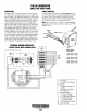
INTERNAL
WIRING
SCHEMATIC
CIRCUIT
BREAKER
A circuit breaker
is
installed
on
all
WESTERBEKE
genera-
tors.
This
circuit
breaker
will automatically
disconnect
gener-
ator
power
in case
of
an electrical
overload.
The
circuit
breaker can be manually
shut
off
when
servicing
the genera-
tor to ensure that no
power
is
coming
into
the
boat.
NOTE:
This circuit breaker is available as a WESTERBEKE
add-on
kif
for earlier
model
generators; contact
your
WEST-
ERBEKE dealer.
BLACK
l1
REMOVE
FOR
50
Hz
CIRCUIT
BREAKER
3
PHASE
TWELVE
WIRE
RECONNECTABLE
r------,
t C t
,--------,
I
I
I
I
I
L
.
I
EXCITER
r - - - + - - - - - - -
..,
A t t B I
I
t
ROTOR
I
+
I
a'
~3
I
1
II
~i
t
I
I
.---:-
I
,
t
1
I
2
I
I t
I
L
___
+
_______
..J
r-----
...J
E
/
,"
~[~~
~7':~
UD
1
.::;
'~:
'"
-U
I
..,..
nr
10
REGULATOR
I
:
STATOR
I
! t
2
:
:
:
3
:
:
:
,
:
:
:
!
:
:
:
6
:
:
./.
•
//
t
t
~
,
---
•
FUSE
6.3AMP
Engines & Generators
34
12
11
10
9
8
o
CIRCUIT
BREAKER
PART
NUMBERS
20
KW
-
60
Hz
NO.
42101
]16
KW
-
50
Hz
NO.
427181
7
Ter~~naf
6
Block
25
KW
-
60
Hz
NO.
42702
[20
KW
-
50
Hz
NO.
427111
5
4
3
2
1
A.
EXCITOR
32
KW
-
60
Hz
NO.
42703
(25
KW
-
50
Hz
NO.
T 0
BI
1.
Exciter
Stator
Windings
B.ROTOR
1. Auxiliary
Windings
a.h.c.
2.
Diodes
3. Main
Rotor
Windings
4.
POZ}
Resistor
C.
MAIN
STATOR
I. Auxiliary Windings
2. - 7
Main
Stator
Windings
3.
Auxiliary
Windings
(AC
to Regulator)
D.
ACTERMINALBOARD
E.
REGULATOR