
Installation manual


GENERATOR
AC
VOLTAGE
CONNECTIONS
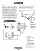
DESCRIPTION
The
regulator is equipped with seven numbered terminals (0
to 6) and their related brass jumpers. The illustrations show
connection points and jumpers for the 3 phase configuration
of
the generator.
The
sensing leads connect between pin
#1
and pin
#2
on the AC terminal block and connection
#2
and
#D
on
the voltage regulator board.
NOTE:
Series Delta requires the installation
of
a jumper on
the regulator board between termillal
Band]
O.
\
J'~
m:
I-
~:
~
170.270V
,.
\
\-
"II
L'
1
~
180.160
V
:
~
\-
+
EXCITE~
~
1---,
1-
__
~60
Hz
D=j
,
3
PHASE
VOLTAGE
REGULATOR
BLK
AVR
CASE GND
BLK
AVR
CASE
GND
PARAllEL
WYE
(STAR)
SERIES
WYE
(STAR)
L-L
-
208
VAC
30
50
Hz
L-N
-120
VAC
10
60
Hz
L-L-
190
VAC
30
50
Hz
L-N
-110
VAC
10
60
Hz
@20
020
L-L-
450
VAC
30
60
Hz
L-N
-
265
VAC
10
60
Hz
L-L-
380
VAC
30
50
Hz
L-N
-
220
VAC
10
50
Hz
BE
THREE
PHASE
(TWELVE
WIRE)
....v-
WESTERBEKE
Engines & Generators
37
H-f--N'GND
U1
V1
W1
Ll
L2
L3
GRN
AVR
H-f--N'GND
U1
V1
W1
L1
L2
L3
GRN GND
BE
THREE
PHASE
(SIX
WIRE)
SERIES
DELTA
L-L-
240
VAC
3060
Hz
L2,
L3-N
-
120
VAC
10
60
Hz
L-L-
220
VAC
30
50
Hz
L2,
L3-N
-
110
VAC
10
50
Hz
A.
SERIES
DELTA
-
Note
the
repositioning
of
Ihe
ground
lead
from
neutral
to
gener-
ator
housing.
J.
Jumper
using
#10
AWG
Wire
.