TECHNICAL MANUAL WESTERBEKE 13 - 21 - 27 - 33 MARINE DIESEL ENGINES Edition Two October 1981
SECTION INDEX GENERAL Introduction Installation Operation Maintenance ENGINE OVERHAUL OTHER OVERHAUL Marine Engine Electrical System Cooling System (External) Transmissions GENERATOR SETS HYDRAULIC CRANKING SYSTEM SERVICE BULLETINS
IMPORTANT PRODUCT SOFTWARE NOTICE Product software of all kinds, such as brochures, drawings, technical data, operator's and workshop manuals, parts lists and parts price lists, and other information, instructions and specifications provided from sources other than Westerbeke, is not within Westerbeke's control and, accordingly, is provided to Westerbeke customers only as a courtesy and service.
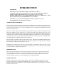
INTRODUCTION IMPORTANT THIS MANUAL IS A DETAILED GUIDE TO THE INSTALLATION, START-UP, OPERATION AND MAINTENANCE OF YOUR WESTERBEKE MARINE DIESEL ENGINE. THE INFORMATION IT CONTAINS IS VITAL TO THE ENGINE'S DEPENDABLE, LONG TERM OPERATION. READ I T ! KEEP IT IN A SAFE PLACE ! KEEP IT HANDY FOR REFERENCE AT ALL TIMES ! FAILURE TO DO SO WILL INVITE SERIOUS RISK, NOT ONLY TO YOUR INVESTMENT BUT YOUR SAFETY AS WELL. UNDERSTANDING THE DIESEL ....
INSTALLATION FOREWORD Since the boats in which these engines are used are many and varied, details of engine installation are equally so. It is not the purpose of this section to advise boatyards and engine installers on the generally well understood and well developed procedures for installation of engines.
In case it is necessary to hoist the engine either front end upwards or reverse gear end upwards, the attachment of slings must be done very carefully to avoid the possibility of damage to the parts on which the weight may bear. It is best if special rigging work be done by someone experienced and competent in the handling of heavy machinery. ENGINE BOLTS It is recommended that bronze hanger bolts of appropriate size be used through the engine flexible mounts.
For all engine models, a propeller half-coupling, bored to shaft size for the specific order, is supplied. The coupling either has a keyway with set screws or is of the clamping type. The forward end of the propeller shaft has a long straight keyway. Any burrs should be removed from the shaft end. The coupling "should be a light drive fit on the shaft and the shat should not have, to be scraped down or filed in order to get a fit.
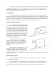
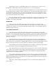
The alignment is correct when the shaft canbe slipped backward and forward into the counterbore very easily and when a feeler gauge indicates that the flanges come exactly together at all points. The two halves of the propeller coupling should be parallel within 0.002 inches (A).
It is essential not to hang too much weight in the form of exhaust system components rigidly from the engine manifold. Generally, it is permissible to directly connect a pipe nipple and a water jacketed exhaust elbow, which two components weigh about 8 pounds (4 kg). If there are more components to be rigidly connected to each other than will weigh 8 pounds, then a flexible exhaust section must be installed between manifold outlet and the exhaust system.
Checking The Back Pressure 1. Exhaust pipe flange 2. Exhaust line 3. Transparent plastic hose, partly filled with water. Measurement "A" may not exceed 39" for normally asperated engines and 19.5" for turbo-charged engines. WATER CONNECTIONS Seacocks and strainers should be of the full flow type at least one size greater than the inlet thread of the sea water pump. The strainer should be of the type which may be withdrawn for cleaning while the vessel is at sea.
FUEL PIPING We recommend copper tubing together with suitable fittings, both for the supply line and the return line. Run the tubing in the longest pieces obtainable to avoid the use of unnecessary fittings and connectors. The shut off valve in the line between the fuel tank and engine should be of the fuel oil type, and it is important that all joints be free of pressure leaks. Keep fuel lines as far as possible from exhaust pipe for minimum temperature, to eliminate "vapor locks".
The transmission control lever may be connected to the pilot station by a flexible, sheathed cable and controlled by a Morse type lever. The single-lever type gives clutch and throttle control with full throttle range in neutral position. The two-lever type provides clutch control with one lever and throttle control with the other. Any bends in the control cables should be gradual. End sections at engine and transmission must be securely mounted.
OPERATION PREPARATION FOR FIRST START The engine is shipped "dry"...with lubricating oil drained from crankcase and fluid from the transmission. Therefore, be sure to follow these recommended procedures carefully before starting the engine for the first time. 1. Remove oil filler cap and fill oil sump with heavy duty diesel lubricating oil to the highest mark on the dipstick. See table under Maintenance for an approved lubricating oil. Do not overfill.
BLEEDING PROCEDURES BY MODEL 1. Initial Engine Start-up (Engine stoppage due to lack-of fuel) a. Insure that the fuel tank(s) is filled with the proper grade of diesel fuel. b. Fill any large primary filter/water separator with-clean diesel fuel that is installed between the fuel tank and engine. To attempt to fill any large primary filter using the manual priming lever on the engine mounted fuel lift pump may prove futile or require a considerable amount of priming. c.
W50 injection pump only. Open the 5/16 bleed screw (Bleed Point D) on the injector line banjo bolt one or two turns and, with, the throttle full open and the engine stop lever in the run position, crank the engine over with the starter until clear fuel free of air flows from this point. Stop cranking and tighten this Bleed screw.
PREPARATION FOR STARTING 1. Check water level in expansion tank. It should be lh to 2 in. below the top of the tank when cold. 2. Check the engine sump oil level. 3. Check the transmission fluid level. 4. See that there is fuel in the tank and the fuel shut-off is open. 5. Check to see that the starting battery is fully charged, all electrical connections are properly made, all circuits in order and turn on the power at the battery disconnect. 6. Check the seacock and ensure that it is open. .
NOTE: Always be sure that the starter pinion has stopped revolving before again re-engaging the starter; otherwise, the flywheel ring gear or starter pinion may be damaged. Ensure that the electrical connection to the cold starting aid is correct . Extended use of the cold starting aid beyond the time periods stated should be avoided to prevent damage to the aid. NEVER under any circumstances use or allow anyone to use ether to start your engine.
TEN MUST RULES IMPORTANT ..for your safety and your engine's dependability. IMPORTANT ALWAYS 1. Keep this Manual handy and read it whenever:;.in doubt. 2. Use only filtered fuel oil and check lube oil level daily. 3. Check cooling water temperature frequently to make sure it is 1900 or less. 4. Close all drain cocks and refill with water before starting out. 5. Investigate any oil leaks immediately. NEVER 6. Race the engine in neutral. 7.
MAINTENANCE PERIODIC ATTENTION:„ After you have taken delivery of your engine, it is important that you make the following checks right after the first fifty hours of its operation. Note: Transmissions generally require fluid change after the first 25 to 30 hours of operation. Refer to the Transmission Section of this manual for details. FIFTY HOUR CHECKOUT (INITIAL) Do the following: 1. Re-torque the cylinder head bolts. 2. Re-torque the rocker bracket nuts and adjust valve rocker clearance. 3.
CAUTION: 6. The use of different brands of lubricating oils during oil changes has been known to cause extensive oil sludging and may in many instances cause complete oil starvation. Start engine and run for 3 or 4 minutes. Stop engine and check ,.oil filter gasket for leaks. Check oil sump level. This is important as it may be necessary to add oil to compensate for the oil that is required to fill the engine's internal oil passages and oil filter. Add oil as necessary. See Note.
14. 15. Disconnect battery and store in fully charged condition. Before storing the battery, the battery terminals and cable connectors should be treated to prevent corrosion. Recharge battery every 30 days. Check alignment.
LUBRICATING OILS Lubricating oils are available for Westerbeke Diesel engines which offer an improved standard of performance to meet the requirements of modern operating conditions such as sustained high speeds and temperatures. These oils meet the requirements of the U. S. Ordnance Specifications MIL-L-2104B (API Service CC). Any other oils which also conform to these specifications, but are not listed here, are, of course, also suitable. S.A.E.
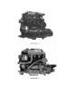
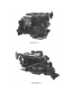
ENGINE OVERHAUL The following sections contain detailed information relating to the proper operation characteristics of the major components and systems of the engine. Included are disassembly, rework and reassembly instructions for the guidance of suitably equipped and staffed marine engine service and rebuilding facilities. The necessary procedures should be undertaken only by such facilities. Additional operating characteristics are included in the Operation Section of this manual.
GENERAL SPECIFICATIONS MODEL,--MARINE - GENERATOR W13 4.4KW W21 7.7KW W27 11.1KW W33 12.5KW TYPE 4 Cycle, Water Cooled, Vertical Overhead Valve Type Diesel Engine NUMBER OF CYLINDERS 2 3 4 4 BORE 70mm 73mm 73mm 78mm STROKE 78mm 78mm 78mm 78mm TOTAL DISPLACEMENT (LITRE) 0.600 0.979 1.305 1.490 MAXIMUM HORSEPOWER @3600 RPM 13.5 21 29 33 LUBE OIL CAPACITY 2.5 litre 3.0 litre 4.0 litre 4.
TABLE OF TIGHTENING TORQUE Cylinder head bolt (M10) W21, W27, W33 (M12) W21 W13, W27 (M14) W33 kg- m 7-8 11-12 12-13 15-16 lb ft. 50.7-57.9 79.6-86.8 86.8-94.0 108.5-115.7 Crank pulley nut 15-20 20-25 108.5-144.6 108.5-180.8 Main bearing cap bolt W21, W27, W33 5.0-5.5 36.-43.4 Connecting rod cap nut W13, W21, W27 3.2-3.5 23.1-25.3 Connecting rod cap bolt W33 11.5-12.5 83.2-90.4 Flywheel bolt 11.5-12.5 83.2-90.4 Oil pan drain plug 5-6 36.2-43.4 Oil filter 1.1-1.3 8.0-9.
STD. VALUE REPAIR LIMIT SERVICE LIMIT 26Kg/cm2 32Kg/cm2 1. Compression pressure @ 280 RPM 32Kg/cm2 2. Compression pressure difference between cylinders (maximum) 2.5Kg/cm2 3. Firing Order 4. Injection Timing - BTDC of compression stroke when started"'-, at smoke set position. Marine Engine 230 +/- 1.50 Generator 190 +/- 1.50 5. Cylinder Head a. b. c. d. e. 6.
STD. VALUE b. Valve head diameter (Exhaust) W13 W21, W27 W33 Overall length W13 W21, W27 W33 25.0 mm 25.2 mm 28.0 mm 103.0 mm 114.5 mm 126.0 mm d. Stem O.D. W13, W21, W27 . W33 6.6 mm 8.0 mm e. Clearance between stem & guide Intake valve Exhaust valve 0.10 mm 0.15 mm f. Valve face angle 450 g. Valve head thickness (margin) W13, W21, W27 W33 1.0 mm 1.5 mm c. 9. 11. SERVICE LIMIT 0.50 mm 0.50 mm Valve Spring a. Free length b. Installed load/length c. 10.
STD. VALUE REPAIR LIMIT SERVICE LIMIT Cylinder bore W13 W21, W27 W33 70.0 mm 73.0 mm 78.0 mm +0.2 mm +0.2 mm +0.2 mm +0.95 mm +0.95 mm +1.20 mm Cylinder bore oversize finish tolerance 0 to 0.03 mm for each oversize tolerance Taper of cylinder bore 0.01 mm or less 12. Piston Type Solid type Material Aluminum alloy O.D. (skirt end) W13 W21, W27 W33 70.0 mm 73.0 mm 78.0 mm Piston to cylinder clearance 13. W13, W21, W27 W33 0.25, 0.50, 0.75 mm 0.25, 0.50, 0.75, 1.
STD. VALUE Ring width Compression rings W13 W21, W27, W33 - Nos. 2 & 3 Oil ring No. 1 No. 2 No. 3 Oil ring Ring gap 2. 5 mm 2.0 mm 0.66-0.11mm 0.05-0.09mm 0.04-0.08mm 0.3 mm 0.2 mm 0.2 mm 0.03-0.07mm 0.2 mm 0.15-0.40mm 1.5 mm Connecting Rod Type Forged I-beam Bend and distortion Big end thrust clearance 16. within 0.15 mm 0.1-0.35mm 0.5 mm Connecting Rod Bearing Type Kelmet metal with back metal Oil clearance 0.15 mm Undersize 17. SERVICE LIMIT 4.
STD. VALUE REPAIR LIMIT SERVICE LIMIT W13 U.S. 0.25 U.S. 0.50 U.S. 0.75 58.695-58.710 mm 58.445-58.460 mm 58.195-58.210 mm W21, W27 U.S. 0.25 U.S. 0.50 U.S. 0.75 51.735-51.750 mm 51.485-51.500 mm 51.235-51.250 mm W33 U.S. 0.25 U.S. 0.50 U.S. 0.75 56.695-56.710 mm 56.445-56.460 mm 56.195-56.210 mm W13 U.S. 0.25 U.S. 0.50 U.S. 0.75 41.700-41.715 mm 41.450-41.465 mm 41.200-41.215 mm W21, W27 U.S. 0.25 U.S. 0.50 U.S. 0.75 41.700-41.715 mm 41.450-41.465 mm 41.200-41.215 mm W33 U.S. 0.25 U.S.
STD. VALUE REPAIR LIMIT Oil clearance 20. 21. 0.15mm Pump Camshaft Driving method Gear drive Bearing Front: ball bearing Rear: cylinder block hole Cam lobe height 44 mm 23 mm Tappet to cylinder block hole clearance 24. 0.15 mm Push Rod Bend 23. -1.0 mm Tappet O.D. 22. SERVICE LIMIT Within 0.3mm Oil Pump Type Trochoid type Check valve opening pressure W13 W21 W27, W33 3.5kg/cm2 6.0kg/cm2 4.
STD. VALUE c. 150 RPM: 33.5 +/- 5.Omm3/stroke 150 RPM: 37.5 +/- 5.Omm3/stroke 150 RPM: 34.0 +/- 5.Omm3/stroke 150 RPM: 36.0 +/- 7.5mm3/stroke d. Difference from reference cylinder 2mm3/rev. cylinder or less e e. Pre-stroke 2.2 +/- 0.1 (within 0.1 for . difference from reference cylinder) f. Timing - see service text g. Nozzle h. 26. 27. SERVICE LIMIT Fuel injection pump rate at start set (MS) W13 W21 W27 W33 Type Model Injection start pressure 25.
ADJUSTMENTS (1) Adjustment of Valve Clearance Pull off the air breather from the rocker cover, and then loosen off rocker cover bolts. Adjust the valve clearance at top dead center of compression stroke (cold) of each cylinder. Prior to the measurement of the valve clearance, re-tighten cylinder head bolts to specified torque.
Adjustments of High Speed (No Load) Set the engine to a no-load high speed with the HIGH SPEED set bolt. This speed is set by the factory and should not require adjustment. Should adjustment be required after the accuracy of the tachometer has been verified by mechanical means, loosen the HIGH SPEED sit bolt lock nut and turn the set bolt clockwise to lessen no load speed and counter-clockwise to increase no load speed. Re-tighten the lock nut. Consult model specifications for no load high speed setting.
CONSTRUCTION AND SERVICING OF CYLINDER HEAD CONSTRUCTION 1. Cylinder Head The cylinder head is an overhead valve head produced from a high rigidity special cast iron having an excellent cool-effect. Intake end exhaust ports are of a cross-flow type which insures good 'intake and exhaust efficiency. The combustion chamber is a swirl chamber produced from heat resisting steel and is press-fitted in the cylinder head. This chamber, therefore, requires no disassembly.
SERVICING THE CYLINDER HEAD DISASSEMBLY Disconnect the air breather hose. Disconnect the fuel injection pipes. Remove the air intake silencer, intake manifold and exhaust manifold. Remove the rocker cover. Remove the rocker arms and rocker shaft assembly. Remove the push rods. Remove the cylinder head assembly by loosening the head bolts in the sequence shown in the figure. Remove the cylinder head gasket. Partly disassemble the cylinder head assembly in the following manner. Remove the nozzle holder.
INSPECTION 1. Cylinder Head Prior to washing the cylinder head, check for cracks, damage and water leaks. Check to see if the oil passageway feeding lube oil to the rocker shaft is clean. Using a straight edge and a feeler gauge, check the lower surface of cylinder head for distortion as shown. 2. Valve Guide Check a valve stem to guide clearance. If the clearance exceeds the service limit, replace the valve guide and valve.
4. Valve Check the valve face and stem for excessive wear, damage and deformation. Correct or replace if defective. If valve head thickness has decreased over the service limit, replace the valve. Check the tip of the valve stem for wear and pitting. Correct if defective. Replace if the tip is worn over the service limit. 5. Valve Spring Check for cracks and damage. Measure the free length and load of the spring. Replace if the spring is deteriorated. Check the squareness of the spring.
Apply oil to the valve stem and insert the valve stem into the valve guide. Install the spring, retainer and retainer lock in order of mention. To assemble the rocker arms and shaft, first place the rocker shaft in such a manner that the identification mark (3 mm hole) at the front end of the shaft faces toward the front of engine. Install the frontmost rocker arm and retain it with a snap ring. Then, install the assembly in the cylinder head.
CONSTRUCTION AND SERVICING OF CYLINDER BLOCK ASSEMBLY 1. Cylinder Block The cylinder block is a special cast iron casting and is of a full jacket type formed integral with cylinder liners. Main bearings are metal-backed copper sintered alloy (kelmet) bearings and are coated with lead and tin alloy plating on the journal surface and flash-plated over the entire bearing surface to insure good run-in. Crankshaft thrust is received by the flanged bearing.
The gear case is an aluminum casting and is attached on the front end of the cylinder block through the front plate. The case houses the injection pump front bearing and related parts of the governor and further serves as a camshaft and idler gear thrust surface.
7. Camshaft and Timing Gear The camshaft is a high carbon steel forging. The cam surface and journals are induction-hardened to improve wear resistance. The shaft is supported on three bearings. Each journal is supported in a bore made in the cylinder block and is lubricated by a forced lubrication system. A camshaft journal has a slot to intermittently lubricate the rocker arms through the cylinder head. Further, the shaft has an oil escape hole at the rear end to let excess oil return to the oil pan.
SERVICING Disassembly For removal of the cylinder head and related parts, refer to "Cylinder Head". For the removal of the water pump and electrical equipment, refer to their respective items. Pull off the push rod, then pull out the tappet upward.. Remove the fuel filter. Loosen the crankshaft pulley nut, then take out the pulley and washer. With flywheel bolts loosened, remove the flywheel. Remove the rear plate and the rear oil seal case.
Remove the connecting rod big end bolt nuts (bolts on the W33), then remove the bearing cap. Push tie piston and connecting rod assembly upward out of the cylinder block. (Mark each piston with its respective cylinder prior to its removal.) Arrange the removed parts by each cylinder. When pushing out the piston and connecting rod assembly, use a wooden block on the mating surface of cap so as not to impair the metal. When disassembling the piston and connecting rod assembly, use the following procedure.
Check the water jacket for scales and rust. Clean if necessary. Check the cylinder wall for scratches, damage and wear. If defective, correct the cylinder by honing or reboring. Measure the cylinder bore size at three levels in the directions of A and B. In case of slight wear of cylinder bore and when only the piston rings require replacement, check the upper part of the cylinder for groove wear. If there is groove wear, remove it by reaming or, when necessary, by honing. 2.
Measure the piston ring gap clearance. Replace the ring if the gap is too large. To measure, insert the ring into the least worn place of the cylinder bore (skirt) using a piston as shown, and measure the gap with a feeler gauge. When the clearance between the piston pin and piston or connecting rod small end bushing for the W33 engine is excessive, replace the piston and pin assembly or the connecting rod. 3. Connecting Rod Using a connecting rod aligner, check bend and distortion of the rod.
4. Crankshaft Measure crankshaft bend. If excessive, replace the crankshaft. Check the journals and pins for damage, seizure and other faults. If the journals and pins are seriously worn, or damaged, correct them to undersize. In this case, it is necessary to replace the main bearings and connecting rod bearings to the same undersize parts. When correcting the crankshaft journals and pins undersize, finish each end to R2.5 mm. Check the crankshaft end play.
Install the main bearings and connecting rod bearings to the cylinder block and connecting rod respectively. Tighten bolts to specification and measure the bearing I.D. Subsequently measure the crankshaft journal and pin O.D. to obtain an oil clearance. (A plasti-gauge may be used.) In case of excessive oil clearance, replace the bearing. If the standard clearance cannot be obtained even after replacement of the bearing, grind the crankshaft undersize and install bearings of the same size.
6. Timing Gears and Injection Pump Gear Check each gear for incorrect tooth contact, wear and damage. Replace if defective. Also check the Oldham's coupling groove at the rear end of the injection pump camshaft for faults. 7. Camshaft Measure the clearance between the camshaft journals and cylinder block. If the clearance is excessive, replace the camshaft or the cylinder block. If the cam surface is damaged or the cam lobe is worn over the service limit, replace the camshaft. 8.
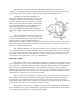
(1) When the camshaft front bushing needs to be pressed in, align the bushing oil hole with the oil hole in the cylinder block as illustrated. To align the oil holes, draw an oil hole mark (with marking ink) on the front end of the cylinder block. After installing the bushing, make certain the oil holes are properly aligned. (2) When the idler gear shaft needs to be pressed in, observe the illustrated direction of installation and length of protrusion.
(6) Check the crankshaft end play. (7) Apply sealant to outside surface of side seals. Press the side seals into the front and rear caps. (Insure the radius ends are installed first and the radius faces towards the outside of the block.) This completes the reassembly of the crankshaft. On the W13 insert the crankshaft into the crankcase. Apply engine oil to the main bearings and crankshaft journals. Be careful not to damage the main bearings.
(9) The piston and the connecting rod should be assembled as described below using Piston Pin Setting Tool (Special Tool), except the W33. (See below.) Insert the piston pin into the push rod of the tool, then screw the guide fully into the push rod. Insert the assembled push rod, piston pin and guide into the piston pin hole from the guide side, and into the small end of the connecting rod.
(10) The piston rings differ in shape from one another. Be careful to install them in proper positions and directions as illustrated and with the stamped manufacturer mark and size mark facing up. In case of the oil ring with coil expander, the gap clearance of the ring should be positioned 180 degrees away from that of the expander. (11) Insert the piston and connecting rod assembly from above into the cylinder block using a ring band.
(15) With the idler gear mating mark "1" properly aligned with the crankshaft mating mark "1", install the idler gear onto the idler shaft. When the crankshaft front bearing has already been installed, the mating mark "1" on the front side of the crankshaft is invisible. Align the idler gear mating mark "1" with a mark line on the side of the gear boss. In this case, after installing the idler gear, press the sealant-coated guide seal into the front and rear main bearing caps.
Insert the o-ring properly into the o-ring groove in the drive gear sleeve. Apply white lube to the outside surface of drive gear shaft (specially to the o-ring area), and then insert the shaft into the sleeve. Keep the gear unit and sleeve in position with a spring pin. The spring pin groove must be directed outward in relation to the shaft center. The pin end must not protrude out of the sleeve outside surface. Install the o-ring in the o-ring groove in the outside surface of the sleeve.
LUBRICATION SYSTEM The lubrication system is a full-force type using a trochoid gear pump fitted with a full-flow oil filter. The oil pump is driven through the Oldham's coupling at the rear end of the fuel injection pump camshaft. The oil from the oil pump flows into the cartridge type oil filter via the relief valve. After being filtered in this filter, the oil passes through the oil gallery hole in the cylinder block, being delivered to each part of the engine.
SERVICING Disassembly (1) 0i1 Filter If the oil filter is on too tight to remove by hand, remove using a filter wrench (commercially obtainable). (2) Oil Pump Remove the oil filter. Remove the pump cover assembly body, o-ring and gasket. Inspection (1) Oil Pump Outer Rotor to Body Clearance: Using a feeler gauge, check an outer rotor to body clearance. If excessive, replace the rotor assembly.
Rotor Clearance: Check an outer rotor to inner rotor clearance using the feeler gauge. If excessive, replace the rotor assembly. Rotor to Cover Clearance: With the outer rotor inserted in the filter body, measure the clearance between the rotor and straight edge using the feeler gauge. In case of excessive clearance, replace either the rotor or the body. Pump Body O-ring: Check pump body o-ring for cracks and damage. REASSEMBLY (1) Oil Pump Install the gasket.
FUEL SYSTEM Fuel from the fuel tank is drawn to the engine by means of an engine mounted 12 volt electric fuel pump/filter. It is also filtered by an engine mounted secondary fuel filter and delivered to the fuel injection pump. The injection pump then delivers a portion of the fuel to each injector through the connecting injection lines where the injector sprays the fuel into the combustion chamber for ignition.
(a) Fuel Injection Control Fuel injection rate is controlled by changing the relative positions of the plunger lead and barrel. The plunger is rotated by the control pinion which is mounted on the plunger barrel. This pinion is in mesh with the plunger lower collar to directly turn the plunger. As the engine runs, the injection pump camshaft rotates to move the control rack through the centrifugal type governor weight, governor sleeve and lever. The control rack slides to turn this pinion.
(d) Delivery Valve Operation The delivery valve functions to deliver the fuel to the injection pipe after the fuel pressure has increased sufficiently high and also to prevent "after-drip" from the nozzle. When the fuel pressure above the plunger has decreased after injection, the delivery valve piston closes the delivery valve seat. At this time the - compressed fuel remaining in the injection pipe drips from the nozzle.
(b) When removing the plunger, first take out the spring retainer (6) from the plunger tube (12). Then remove the washer (7), 0-ring seal (8), valve (9), plunger spring (10) and plunger (11) from the tube. Wash the removed parts with detergent and blow off dirt with compressed air. CAUTION: THE TUBE (12) HAS VERY SMALL WALL THICKNESS. BE CAREFUL NOT TO DEFORM THE TUBE DURING REMOVAL OF THE PLUNGER AND THE RELATED PARTS. CAREFULLY HANDLE THE PLUNGER TO PREVENT IT FROM BEING DENTED OR OTHERWISE DAMAGED.
(1)Remove the delivery valve holder. (2)Take out the valve spring, valve and O-ring. (3)Take out the gasket and valve seat. (4)Spread the lock plate of the tappet guide pin. Push the tappet slightly in and pull off the guide pin using a pincette. Then remove the tappet. (5)Remove the spring and upper seat. (6)Remove the pinion. (7)Pull out the plunger barrel upward from the pump housing. Assemble the removed plunger barrels and plungers by each cylinder. (Do not mix plungers and barrels of other cylinders.
INSPECTION (1)Fuel Filter (Secondary) Check the element for clogging and dirtiness. Replace if it is, seriously damaged. Regular element replacement interval is 200 hours. Replace the element more frequently if engine operating condition is severe. (2)Fuel Pump (a) Filter and Valve Check the filter element for clogging and dirtiness and the valve plunger and spring for damage and dirtiness. Element replacement interval is same as above.
(c) Control Rack and Pinion If the rack and pinion have any worn or damaged teeth, replace. (d)Tappet Check the tappet O.D. roller and shaft for wear and damage. If defective, replace. (4)Nozzle (a) Check the nozzle for incorrect contact and damage. Replace the nozzle as an assembly if defective. (b)Check the pressure spring for damage. (5)Others Check the set plates and set springs for wear and damage. REASSEMBLY (1)Fuel Filter (Secondary) (a) Install the element and filter cup 0-ring properly in place.
(d)Install the control rack. (e) Install the pinion with its deep root tooth aligned with an aligning mark on the rack. (f) Install the spring upper seat and spring. (g) Assemble the spring lower seat to the plunger. Insert the Mark "L" area of the plunger collar into the control rack side. (h) Insert the tappet, using care not to drop the shim. Align the tappet guide hole with the dowel pin hole of the housing and insert the tappet guide pin.
(d)Check fuel injection timing. For adjustment procedure, refer to Adjustment in the GENERAL section. (5)Partial Reassembly of Nozzle and Nozzle Holder Assembly CAUTION: THOROUGHLY CLEAN ALL PARTS WITH DIESEL OIL. DO NOT WIPE THEM WITH RAGS. WHEN TIGHTENING THE RETAINING NUT ON THE NOZZLE .HOLDER BODY, BE SURE TO TIGHTEN IT TO THE SPECIFIED TORQUE. INSUFFICIENT TORQUE WILL CAUSE POOR COMPRESSION. IF TORQUED EXCESSIVELY, THE NOZZLE NEEDLE WILL DRAG, AFFECTING INJECTION CHARACTERISTIC.
(c) After-spilling Test An injection nozzle is considered defective if it spills fuel accumulated on the bottom of the nozzle after chattering test. Replace such a nozzle. A very small amount of fuel may sometimes remain on the tip of the nozzle. This is due to chattering and is not a faulty nozzle. (d) Install the tested nozzle holder assembly in the cylinder head. Tighten bolts to the specified torque. Be sure to install the assembly together with a new gasket.
GOVERNOR SYSTEM l: CONSTRUCTION Operation of the governor maintains the engine speed constant as the centrifugal force acting on the governor weights, according to the engine speed balances with the tension of the governor spring. If the engine speed increases, the governor weights will open, forcing the sliding shaft forward. Therefore, the injection pump control rack, linked to the sliding shaft through the governor lever assembly, tie rod and spring, is moved in the direction that less fuel is injected.
2. SERVICING Disassembly 1. 2. 3. 4. 5. 6. 7. 8. 9. Remove the alternator belt. (Refer to COOLING SYSTEM.) Remove the crankshaft pulley nut, and then remove the pulley. Remove the fuel injection pump. (Refer to "Fuel Injection Pump.) Remove gear case mounting bolts, then remove the gear case. ( See CAUTION in "Removal" of cylinder block gear case.) Remove the governor spring. Remove the nut, washer and lever C. Remove the speed control lever from the gear case.
Reassembly 4. Needle Bearing Check the needle bearing supporting the governor lever shaft in the gear case for damage. Reassembly is just the reverse of disassembly. After reassembly, check the governor for smooth movement.
ELECTRICAL SYSTEM CONSTRUCTION 1. Starter The starter can be roughly divided into the following sections: (a) A motor section which generates a drive power. (b) An overrunning clutch section which transmits an armature torque, preventing engine overrun after starting (c) A switch section which is operated when actuating the overrunning clutch through a lever and which supplies load current to the motor.
2. Alternator (50 amp 12 volt) The alternator is a three phase AC generator with a diode rectifier and is driven by the crankshaft through a pulley and a V-belt. It can also be roughly divided into rotor and stator sections. The rotor section consists of a rotor, ball bearings and pulley with a fan, while the stator section consists of an armature, front and rear brackets, fin complete and brushes. Three diodes (+) and three diodes (-) are fixed on the fin heat sink. 3.
DISASSEMBLY 1. Starter (a) (b) (c) Turn the engine battery selector switch to the off position. Disconnect wiring from Band S terminals on the starter. Remove attaching nuts, then remove the starter. 2. Alternator (a) (b) (c) (d) Turn the engine battery selector switch to the off position. Loosen the alternator adjusting strap bolts, then remove the belt. Disconnect electrical connections from back of alternator. (Note connections for proper reassembly.) Remove alternator support bolt.
(c) Brushes and Brush Holders (i) Check brushes. If the brushes are worn over the service limit, replace. (See "Service Standards".) (ii) With the holders assembled to the commutator, check spring tension. If spring tension has decreased over the service limit, replace. (iii) Check continuity between the positive brush holder and the brush holder base. In case of continuity, replace the holder assembly. (iv) Check the brush holder caulk. (d) Armature (i) Check the armature coil using a growler tester.
(f) Solenoid Switch The solenoid switch must be conducting between S and M terminals and between S terminal and body. (g) Overrunning Clutch If the pinion is worn or damaged, replace. (h) Reduction Gear Replace the reduction gear if it is worn or damaged. (i) Front Bracket If the ball bearing seat or pinion shaft bushing is worn, replace the bracket assembly. (j) Pinion Gap (i) Remove the connector from M terminal.
(k) Pinion Shaft Thrust Gap A pinion shaft thrust gap is an axial play of the shaft. Adjust the gap to less than 0.5 mm by the adjusting washer between the center bracket and the reduction gear. (i) When Pinion has been Removed After installing the reduction gear to the pinion shaft, insert the pinion shaft into the center bracket, and then fix the pinion shaft with a washer and a snap ring. With the pinion shaft pressed to one side, measure the thrust gap and adjust by the adjusting shim.
(ii) Holding Test With the battery connected between the S terminal of the solenoid switch and the body, manually move the pinion out of the stopper position. If the pinion does not move back to its original position, the switch is good. (iii) Return Test With the battery connected between the M terminal of the solenoid switch and the body, manually move the pinion out of the stopper position. If the pinion returns to its original position as soon as it is released, the switch is good.
Because of the use of IC's (integrated circuits), the electronic voltage-regulator is very compact and is built in the rear bracket of the alternator. Charging Voltage Test 1. 2. 3. 4. 5. Turn key switch off on marine engines or disconnect the oil pressure switch wire on generator sets. Disconnect cable from positive (+) terminal of battery and connect an ammeter in series between the cable and positive (+) terminal of the battery. Connect a voltmeter between terminal (L) of alternator and ground.
8. Description Standard value Charging voltage 14.4 +0.3V at 20'C (68'F) Temperature compensation gradient -O.1V/10'C (50'F) If the ammeter reading is more than 5A, continue to charge the battery until the reading falls to less than 5A or replace the battery with a fully charged one. An alternative method is to limit the charging current by connecting 1/4 ohm (25W) resistor in series with the battery. Output Test 1. Disconnect the battery ground cable. 2.
Disassembly 1. After removing the three through bolts, insert a screwdriver between the front bracket and stator. While prying it, remove the front bracket and rotor. NOTE: If the screwdriver is inserted too deep, the stator coil might be damaged. 2. Hold the rotor in a vise and remove the pulley nut. Then remove the pulley, fan, spacer and seal. Next, remove the rotor from the front bracket and remove the seal. 3. Unsolder the rectifier from the stator coil lead wires and remove the stator assembly.
3. Insert a #2 Philips screw driver through this opening and remove the two screws holding the rectifier. 4. Remove the nut anchoring the "B" terminal bolt and the capacitor mounted thereto on the outside rear of the bracket. Then remove the third Philips screw holding the brush-holder to the bracket. 5. Carefully withdraw stator, brush-holder and rectifier from the rear bracket as one loosely connected unit.
2. Check for continuity between the field coil and slip ring. If there is no continuity, the field coil is defective. Replace the rotor assembly. 3. Check for continuity between the slip ring and shaft (or core). If there is continuity, it means that the coil or slip ring is grounded. Replace the rotor assembly. Stator Assembly 1. Check for continuity between the leads of the stator coil. If there is no continuity, the stator coil is defective. Replace the stator assembly. 2.
Rectifier Assembly (+) Heatsink Assembly Test Check for continuity between the (+) heatsink and stator coil lead connection terminal with an ohm-meter. If there is continuity in both directions, the diode is short circuited. Replace the rectifier assembly. (-) Heatsink Assembly Test Check for continuity between the (-) heatsink and stator coil lead connection terminal. If there is continuity in both directions, the diode is shortcircuited. Replace the rectifier assembly.
Brush and Brush Rig 1. Check the length of the brush. A brush worn down to the service limit line should be replaced. Description Length of brush Load of brush spring Standard value Service limit 18 mm (.709 in.) 8 mm (.315 in.) 3.04 to 4.22 N 2.06 N (.5 lbs.) (.7 to 1 lbs.) --- 2. Check the brush spring pressure to make sure the brush moves smoothly in the brush holder. Reassembly Reverse the disassembly procedure but pay special attention to reassembly of the following. 1.
4. Glow Plug 'When the positive cable of the battery is connected to the glow plug terminal and the negative cable of the body, the glow plug must glow red hot. Reassembly 1. Starter CAUTION: PRIOR TO INSTALLATION, CLEAN THE STARTER FLANGE AND CRANKCASE MOUNTING SURFACE THOROUGHLY BY REMOVING ALL OIL, PAINT AND RUST. THE STARTER PERFORMANCE LARGELY DEPENDS ON THE QUALITY OF WIRING. USE WIRE OF SUFFICIENT SIZE AND GRADE BETWEEN THE BATTERY AND THE STARTER AND FULLY TIGHTEN EACH TERMINAL. 2.
MAINTENANCE 1. Judging , Engine Overhaul Period Generally the time at which an engine should be overhauled is determined by lowered engine power, decreased cylinder compression pressure and increased fuel and lubricating oil consumption. The lowered engine power, in the case of diesel engines, is not necessarily due to a trouble of the engine itself but is sometimes caused by worn or damaged injectors and/or worn or damaged injection pump.
2. Measuring Compression Pressure 1. Remove the glow plug of cylinder to be measured. 2. Attach a pressure gauge adapter in the screw hole of the glow plug and connect a pressure gauge. 3. Operate the starter. Read the engine rpm and pressure gauge when the starter speed has become constant. Standard value is 32kg/cm2 at 280 RPM. Cylinder and/or valve overhaul may be required should this value fall to 26kg/cm2 or below. 4. Measure the compression pressure of other cylinders in a similar manner.
5. Disassembling Cautions When disassembling, keep in mind the following cautions. Note that the order of disassembly and reassembly will vary with change of specifications. 1. 2. 3. 4. 5. Before disassembly and cleaning, carefully check for defects which cannot be found after disassembly and cleaning. Before disassembly, drain all drain water, oil and fuel. Check dirtiness of the oil. Clean or wash the engine exterior. Do not disassemble or remove the parts that require no disassembly.
OTHER OVERHAUL CONTENTS SECTION MARINE ENGINE ELECTRICAL SYSTEM Q Activation by Keyswitch (1980 onwards) COOLING SYSTEM EXTERNAL R TRANSMISSIONS S Type HBW Short Profile Sailing Gear Type BW Transmission
SECTION Q MARINE ENGINE ELECTRICAL SYSTEM ACTIVATION BY KEY SWITCH This system is supplied on most Westerbeke engines beginning May, 1980. Essentially, activation of the circuit is accomplished by the ignition position of the keyswitch. No oil pressure switch is required. The engine is preheated by turning the keyswitch to the ON position, then depressing the key. The engine is cranked by turning the keyswitch to the right-most momentary position.
SECTION R COOLING SYSTEM (EXTERNAL) 1. DESCRIPTION Westerbeke marine diesel engines are equipped with fresh water cooling. Transfer of heat from engine fresh water to sea water is accomplished by a heat exchanger, similar in function to an automotive radiator. Sea water flows through the tubes of the heat exchanger while fresh water flows around the tubes. The sea water and fresh water never mix with the result that the cooling water passages in the engine stay clean. 2.
5. SEA WATER PUMP IMPELLER REPLACEMENT The following instructions are general and indicative only. Specific instructions where applicable may be packaged with your replacement impeller. a. b. c. d. e. f. g. Remove the front cover gasket taking care to salvage the gasket. Remove the impeller by pulling straight outwards, parallel to the pump shaft. This is best done with a pair of pliers applied to the impeller hub. Coat the replacement impeller and the chamber into which it mounts with grease.
8. THERMOSTAT Generally, thermostats are of two types. One is simply a choking device which opens and closes as the engine temperature rises and falls. The second type has a by-pass mechanism. Usually this is a disc on the bottom of the thermostat which moves downward to close off an internal by-pass passage within the head. Both types of thermostats, from 1980 onwards, have a hole punched through them to serve as a by-pass while the engine is warming up.
c. d. Remove water connectors from the ends of the manifold and the end plates. Be sure to note the proper location and arrangement of each for proper replacement. Examine all parts lor defects, corrosion and wear and replace as a needed.. REASSEMBLY a. If the manifold was removed as an assembly and left intact, it can be replaced on the cylinder head in the reverse order of removal. Do not reuse the gaskets; install new ones and torque the bolts or nuts to the proper specification (10-12 lb-ft).
SINGLE PASS MANIFOLD Note: Drawing is indicative only. Specific models may vary in detail.
SECTION S TRANSMISSIONS HBW SHORT PROFILE SAILING GEAR DESCRIPTION 1. BRIEF DESCRIPTION The Type HBW Short Profile Sailing Gears are equipped with a positively driven, mechanically operated helical gearing system. The servo-operated multiple-disc clutch requires only minimum effort for gear changing, making the transmission suitable for single-lever remote control via a rod linkage, Morse or Bowden cable.
An oil filler screw with dipstick and an oil drain plug are screwed into the gear casing. The filler screw is provided with a breather hole. The shaft for actuating the multiple-disc clutch extends through a cover on the side of the gear casing. 3. GEAR SETS The transmission is equipped with shaved, casehardened helical gears made of forged low-carbon alloy steel. The multi-spline driving shaft connecting the transmission with the engine is hardened as well.
- FUNCTION The transmission uses a positively driven, mechanically operated multiple-disc clutch system mounted on the output shaft. The thrust force required for obtaining positive frictional engagement between the clutch discs is provided by a servo system.
5. SHAFT BEARINGS Both the input and the output shafts are carried in amply dimensioned taper roll bearings. The intermediate gear and the movable gears are carried in sturdy needle roller bearings. 6. SHAFT SEALS External sealing of the input and output shafts is provided by radial sealing rings. The running surface on the shafts is casehardened. 7. LUBRICATION The transmissions are immersion-lubricated. The bearings are generously supplied with splash oil and oil mist. INSTALLATION 1.
2. PAINTING THE GEARBOX ALWAYS COVER THE RUNNING SURFACES AND SEALING LIPS OF THE RADIAL SEALING RINGS ON BOTH SHAFTS BEFORE PAINTING. Make certain that the breather hole on the oil filler screw is not closed by the paint. Indicating plates should remain clearly legible. 3. CONNECTION OF GEARBOX WITH ENGINE A torsio-elastic damping plate between the engine and the transmission is to compensate for minor alignment errors and to protect the input shaft from external forces and loads.
6. OPERATION OF GEARBOX Gear changing requires only minimum effort. The gearbox is suitable for single lever remote control. Upon loosening the retaining screw, the actuating lever (see illustration) can be moved to any position required for the control elements (cable or rod linkage). Make certain that the lever does not contact the actuating lever cover plate (9): the minimum distance between lever and cover should be 0.5 mm.
The position of the cover plate underneath the actuating lever is factory-adjusted to ensure equal lever travel from neutral position to A and B. Therefore, do not loosen the capscrews mounting this assembly. When installing the gearbox, make certain that shifting is not impeded e.g. by restricted movability of the cable or rod linkage, by unsuitably positioned guide sheaves, too small bending radius, etc. 7.
2. OPERATING TEMPERATURE The maximum permissible temperature of the transmission oil is 130'C. If this temperature is to be exceeded, an optional oil cooler is available. 3. OPERATION OF GEARBOX The zero position of the operating lever on the control console must coincide with the zero position of the actuating lever on the transmission. Shifting is initiated by a cable or rod linkage via the actuating lever and an actuating cam.
2. OIL QUANTITY HBW 5 approximately 0.4 liter HBW 10 approximately 0.6 liter HBW 20 approximately 0.8 liter HBW 50 approximately 0.3 liter HBW 100 approximately 0.35 liter HBW 150 approximately 0.55 liter HBW 150V approximately 1.0 liter HBW 220 approximately 0.75 liter Use the index mark on the dipstick as a reference. 3. OIL LEVEL CHECKS Check the oil level in the transmission daily. Correct oil level is the index mark on the dipstick (see item 1 under OPERATION).
BW TRANSMISSIONS (BW3, BW&, BW12) These manual transmissions rotate opposite to the engine when in forward gear. Shifting effort is very low. The input power on the BW3 is transmitted to the output shaft by helical spur gears when in forward. In reverse this task is taken over by a high performance roller chain. The unit also incorporates a servo cone-type clutch. The BW7 and BW12 transmit their power with casehardened helical gears and in reverse there is an intermediate gear.
SECTION T GENERATOR SETS MANUAL STARTER DISCONNECT (TOGGLE SWITCHES)
MANUAL STARTER DISCONNECT (TOGGLE SWITCHES) GENERAL: This manually controlled series of Westerbeke marine diesel generators is equipped with toggle switches on the engine control panel and, optionally, at remote panels. The following instructions and methods of correcting minor problems apply only to such toggle switch controls. All three switches are momentary contact type and serve the following functions: 1. Preheat: The PREHEAT/DEFEAT toggle switch is a double pole, single throw switch.
REMOTE ENGINE OPERATION: For remote operation of the generator system, the same three switches are used. The PREHEAT and START switches are connected in parallel with the local panel switches and serve the same functions as in the local panel. The STOP switch is in series with the local panel STOP switch, and serves the same functions as in the local panel. The generator may be stopped from local or remote positions.
TROUBLESHOOTING MANUAL STARTER DISCONNECT (TOGGLE SWITCHES) CIRCUIT PROTECTION: The engine control system is protected by a 20 amp manual reset circuit breaker located on the engine as close as possible to the power source. An additional circuit breaker is located at the fuel solenoid (P/N 23041) when this solenoid is used. (This solenoid is not used on models which have a solenoid built into the injection pump.
Battery runs down High resistance leak to ground Check wiring. Insert sensitive (0-.25 amp) meter in battery lines. (Do not start engine.) Remove connections and replace until short is located. Low resistance leak to ground Check all wires for temperature rise to locate fault. Alternator Disconnect alternator at output, after a good battery charging. If leakage stops, replace alternator protective diode plate. That failing, replace alternator.
4.4 - 7.7 - 11.1 - 12.5 KW GENERATOR SETS TECHNICAL DATA 4.4KW 7.7 KW 11.1KW 12.5KW 115 VAC 115 or 115/230 VAC 115 or 115/230 VAC 115 or 115/230 VAC Frequency 60 Hz RPM 1800 34.7 AMP at 115 VAC 33.5 AMP at 230 VAC 48.2 AMP at 230 VAC 54.3 AMP at 230 VAC Voltage Normal Maximum - No load Minimum - Full load 115 VAC 132 VAC 108 VAC Excitation Voltage 115 VAC Separately Excited 12 VDC to Field (Approximately 50 to 70 VAC) Field Coil Resistance 4.4KW 7.7KW 11.1KW 12.5KW 32.5ohms +/-1.7 ohms 22.
FLASHING THE FIELD The generator is equipped with a silicon rectifier for excitation and to flash the field, connect a 12 volt battery between ground and the cathode (terminal with red dot) of the rectifier. Note: only touch the rectifier terminal for a moment.