
Technical data


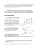

The alignment is correct when the shaft canbe slipped backward and forward into the
counterbore very easily and when a feeler gauge indicates that the flanges come exactly together at all
points. The two halves of the propeller coupling should be parallel within 0.002 inches (A).
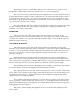
In making the final check for alignment, the
engine half coupling should be held in one position and
the alignment with the propeller coupling tested with the
propeller coupling in each of four positions, rotated 90
0
between each position. This test will also check whether
the propeller half coupling is in exact alignment on its
shaft. Then, keeping the propeller coupling in one
position, the alignment should be checked rotating the
engine half coupling to full position each 90
0
from the next
one.
The engine alignment should be rechecked after
the boat has been in service for one to three weeks and, if
necessary, the alignment remade. It will usually be found
that the engine is no longer in alignment. This is not
because the work was improperly done at first but because the boat has taken some time to take its final.
shape, and the engine bed and engine stringers have probably absorbed some moisture. It may even be
necessary to re-align at a further period.
The coupling should always be opened up and the bolts removed whenever the boat is hauled out
or moved from the land to the water, and during storage in a cradle. The flexibility of the boat often puts
a very severe strain on the shaft or the coupling or both when it 'is being moved. In some cases the shaft
has actually -been .bent by these strains. This does not apply to small boats that are hauled out of the
water when not in use, unless they are dry for a considerable time.
EXHAUST SYSTEM
Exhaust line installations vary considerably and each must be designed for the particular job. The
general requirements are to provide an outlet line with a minimum of restrictions and arranged so that sea
water, rain water or condensation cannot get back into the engine. There should be a considerable fall in
the line between the exhaust manifold flange and the discharge end. This slope in the pipe makes it
difficult for water to be driven in very far by a wave, and a steep drop followed by a long slope is better
than a straight gradual slope. Avoid any depression or trough to the line which would fill with water and
obstruct the flow of exhaust gas. Also avoid any sharp bends.
Brass or copper is not acceptable for wet exhaust systems, as the combination of salt water and
diesel exhaust gas will cause rapid deterioration. Galvanized iron fittings and galvanized iron pipe are
recommended for the exhaust line. The exhaust line must be at least as large as the engine exhaust
manifold flange and be increased in size if there is an especially long run and/or many elbows. It should
be increased by 1/2" in I.D. for every 10 feet beyond the first 10 feet.
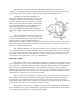
Most exhaust systems today use a water lift type muffler such as the Westerbeke "Hydro-Hush".
In most installations there is a dry, insulated high loop after the engine manifold and before the muffler to
prevent water flowing backwards into the engine during cranking
.