
Technical data
BLEEDING PROCEDURES BY MODEL
1. Initial Engine Start-up (Engine stoppage due to lack-of fuel)
a. Insure that the fuel tank(s) is filled with the proper grade of diesel fuel.
b. Fill any large primary filter/water separator with-clean diesel fuel that is
installed between the fuel tank and engine. To attempt to fill any large primary
filter using the manual priming lever on the engine mounted fuel lift pump may
prove futile or require a considerable amount of priming.
c. Turn the fuel selector valve to "On". Systems with more than one tank insure that
fuel returning is going to the tanks being used.
The above procedures are basic for all initial engine start-ups or for restarting engines stopping due to
lack of fuel.
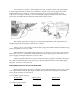
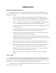
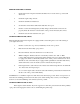
WESTERBEKE W7 AND WPD4 GENERATOR (3600 RPM) (Figure 1)
1. With the use of a 5/16 box wrench or common screw driver, open the bleed screw one or two
turns on the outgoing side of the engine mounted secondary fuel filter (Bleed point A). With firm
strokes on the lift pump priming lever, bleed until fuel free of air bubbles flows from this point.
Stop priming and gently tighten the bleed screw.
2. With a 5/8 open end wrench loosen one to two turns the nut securing the injector line to the
injector (Bleed point B).
Decompress the engine with the lever on the top of the cylinder head. Crank the engine over with
the starter. (W7: ensure that the engine stop lever is in the run position and the throttle is full
open.) (4KW: use the defeat position while cranking.) Crank the engine until fuel spurts by the
nut and line. Stop cranking and tighten the 5/8 nut and proceed with normal starting procedures.
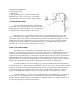
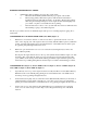
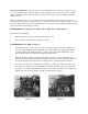
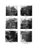
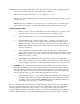
WESTERBEKE W30 (Figure 2), W40 & WPO10, 12h, 15 (Figure 3), W50 & WBO 15 (Figure 4),
W80 & BR 30 (Figure 5),W120 & BR 45 (Figure 5)
1. Open the banjo bolt on top of the engine mounted secondary fuel filter 1-2 turns (Bleed Point A).
With firm stroke on the fuel lift pump priming lever, bleed until fuel free of air bubbles flows
from this point. Stop priming and tighten the bolt.
2. On the fuel injection pump body is a 5/16 bleed screw (Bleed Point B). This may be mounted on
a manifold with a pressure switch. Open this one or two turns (do not remove it) and with the
priming lever bleed until fuel free of air bubbles flows. Stop priming and tighten the bleed screw.
3. On the control cover of the injection pump (Bleed Point C) is a 5/16 bleed screw. Open this
screw one to two turns and proceed as in Step 2. (Note: Bypass this bleed point on the W30
injection