
Technical data
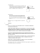
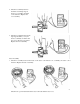
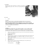

3. Insert a #2 Philips screw driver through this
opening and remove the two screws holding
the rectifier.
4. Remove the nut anchoring the "B" terminal
bolt and the capacitor mounted thereto on the
outside rear of the bracket. Then remove the
third Philips screw holding the brush-holder to
the bracket.
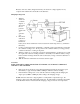
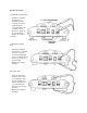
5. Carefully withdraw stator, brush-holder and
rectifier from the rear bracket as one loosely
connected unit.
With the bracket out of the way, it is easy to
unsolder the stator winding leads from the
rectifier quickly to avoid heat damage to the
diodes and I.C. chips. It is also easier to renew brushes because there is no need to-bend the
connecting plates between the brush-holder and the rectifier and possible damage the rectifier
molding.
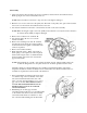
When reversing this procedure, make sure that the stator winding leads are gently pushed back (from
possible contact with the rotor body) after seating the stator into the rear bracket.
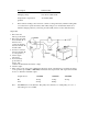
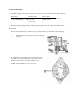
Inspection
Rotor Assembly
1. Check the outside circumference of the slip ring for dirtiness and roughness. Clean or polish with fine
sandpaper, if required. A badly roughened slip ring or a slip ring worn down beyond the service limit
should be replaced.
Description Standard value Service limit
mm (in.) mm (in.)
Slip ring O.D. 33 (1.2992) 32.2 (1.2677)
Runout 0.03 (.0012) 0.2 (.008)
or less