OPERATOR'S MANUAL WESTER8EKE 358 THREE, 388 FOUR, 428 FOUR MARINE DIESEL ENGINES Publication # 37435 Edition One March 1988 ~ WESI'ERBEKE WESTERBEKE CORPORATION AVON INDUSTRIAL PARK, AVON. MA 02322.
SAFETY PRECAUTIONS The following symbols appear in this manual to call attention to and emphasize conditions potentially dangerous to the • operator, Use Extreme Care When Handling Engine Filel (A constant danger of explosion or fire exists) Do not fill fuel tank{s) while the engine is running. Do not smoke or use an open flame near the engine or the fuel tank. IIWARNINGII The above symbol is used in the manual to warn of possible serious personal injury or loss of life.
IMPORTANT PRODUCT SOFTWARE DISCLAIMER Product software 01 all kinds, such as brochures, drawings, technical data, operator's and workshop manuals, parts lists and parts price lists (and other related information), instructions and specifications provided from sources other than Westerbeke, Is not within Westerbeke's control and, accordingly, is provided to Westerbeke customers only as a courtesy and service.
FOREWORD Thank you for selecting a Westerbeke marine product for your use. We at Westerbeke are pleased to have you as a customer. Read this manual carefully and observe ali safety precautions included throughout.
TABLE OF CONTENTS Section ..........................................................................Page W 358 THREE MARINE DIESEL ENGINE GENERAL SPECIFICATIONS .......................................... 12 W 35B THREE SYSTEM SPECiFiCATIONS .................... 13 W 38B FOUR MARINE DIESEL ENGINE GENERAL SPECIFICATIONS .......................................... 15 W 38B FOUR SYSTEM SPECiFiCATIONS ...................... 16 W 42B FOUR MARINE DIESEL ENGINE GENERAL SPECIFICATIONS ...............................
TABLE OF CONTENTS (CONTINUED) LAY-UP & RECOMMISSIONING ......................................89 TABLE OF STANDARD HARDWARE TIGHTENING TORQUES ..................................................93 TORQUE SPECiFiCATIONS .............................................94 SPARE PARTS ..................................................................95 INDEX ................................................................................
GENERAL Introduction This manual contains the equipment operating procedures as well as additional information needed to help the operator keep the equipment in proper working order. Study and follow the instructions carefully. A planned maintenance program is included in this manual; adhering to the program will result in better equipment performance and longer equipment life. Proper diagnosis of a problem is the most important step to satisfactory repair; therefore, a troubleshooting table is included.
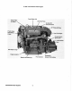
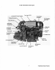
W 358 THREE Marine Diesel Engine Fresh Water Fill Fresh Water Air Bleed Unit Data Plate 20 Amp DC Circuit Breaker 90· Exhaust Elbow Fresh Water Circulating Pump Heat Exchanger Transmission Shift Lever Sea Water Pump Engine Isolator Starter with Solenoid Westerbeke Diesel Engines DC Battery Ground Connection
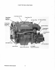
W 35B THREE Marine Diesel Engine 20 Amp DC Circuit Breaker Top Lube Oil Fill Fresh Water Air Bleed Preheat Solenoid DC Charging Fuel. Lift Pl,!mp Instrument Connections Side Lube Oil Fill Secondary Fuel Filter ---....;::....
W 38B FOUR Marine Diesel Engine Top Engine Oil Fill Starter Westerbeke Diesel Engines
W 388 FOUR Marine Diesel Engine Top Engine Oil Fill Air Intake SilElnCler Fuel Lift pump Connections Secondary Fuel Filter'---Zinc Anode - _"___'_ Oil Throttle lever lube Oil Dipstick lube Oil Filter Oil Pressure Sender Oil Pressure Switch Westerbeke Diesel Engines
W 4213 FOUR Marine Diesel Engine Top Engine Oil Fill 90° Exhaust Elbow Lever Starter Westerbeke Diesel Eng ines 10
W 428 FOUR Marine Diesel Engine Top Oil Fill Fuel Lift pump Fuel Filler Zinc Anode Oil Throttle lever Lube Oil Dipstick Oil Pressure Sender Lube Oil Filler 11 Oil Pressure Switch Westerbeke Diesel Engines
W 358 THREE MARINE DIESEL ENGINE GENERAL SPECIFICATIONS Engine Type Diesel, four-cycle, three-cylinder, fresh water-cooled, vertical, in-line (32 hp at 3600 rpm, maximum) Governor Mechanical, centrifugal weight type Valve Mechanism Overhead Combustion Chamber Swirl chamber type Bore & Stroke 3.07 x 3.07 inches (78 x 78 mm) Piston Displacement 68.23 cubic inches (1.
W 35B THREE SYSTEM SPECIFICATIONS FUEL SYSTEM Open flow, totally self-bleeding Fuel No.2 diesel oil (cetane rating of 45 or higher) Injection Pump Nippondenso (Bosch M type) Injection Timing 23" ± OS BTDC (Static) Nozzle Throttle type Injection Starting Pressure 2275 psi (160 kg/cm2) Lift Pump (with filter element) 12-Volt DC; lift capac~y 6 ft (1.
W 358 THREE SYSTEM SPECIFICATIONS Operating Oil Pressure 35 - 55 psi (2.46 - 3.86 kg/cm 2) Oil Grade API specijication CC or CD ELECTRICAL SYSTEM Starting Battery 12-Volt, 35 A-H, (-) negative ground (recommended) (45 A-H cold areas) Battery Capactty 90 - 125 (Ampere-Hours) Starting Aid 12-Voit sheathed type glow plug Starter Motor 12-Volt, 1.2KW, solenoid, actuated shift DC No-Load Current 60 Amps at 11.5 Volts (6500 rpm, min.
W 38B FOUR MARINE DIESEL ENGINE GENERAL SPECIFICATIONS Engine Type Diesel, four-cycle, four-cylinder, fresh water-cooled, vertical, in-line (37 hp at 3600 rpm, maximum) Governor Mechanical, centrifugal weight type Valve Mechanism Overhead Combustion Chamber Swirl chamber type Bore & Stroke 2.87 x 3.07 inches (73 x 78 mm) Piston Displacement 79.64 cubic inches (1.
W 38B FOUR SYSTEM SPECIFICATIONS FUEL SYSTEM Open flow, totally self-bleeding Fuel No.2 diesel oil (cetane rating of 45 or higher) Injection Pump Nippondenso (Bosch M type) Injection Timing 23° ± OS BTDC (Static) Nozzle Throttle type Injection Starting Pressure 2275 psi (160 kg/cm2) Lift Pump 12-Volt DC; lift capacity 6 ft (1.8 m) Fuel Filter (on engine) Canister type, with replaceable element Air Cleaner Metal screen type - cleanable Air Flow (engine combustion) 82.9 cfm (2.
W 38B FOUR SYSTEM SPECIFICATIONS Operating Oil Pressure 35 - 55 psi (2.46 - 3.86 kg/cm 2) Oil Grade API specification CC or CD ELECTRICAL SYSTEM Starting Battery 12-Volt, 35 A-H, (-) negative ground (recommended) (45 A-H cold areas) Battery Capacity 90 - 125 (Ampere-Hours) Starting Aid 12-Volt sheathed type glow plug Starter Motor 12-Volt, 1.2KW, solenoid, actuated shift DC No-Load Current 60 Amps at 11.5 Volts (6500 rpm, min.
W 42B FOUR MARINE DIESEL ENGINE GENERAL SPECIFICATIONS Engine Type Diesel, four-cycle, four-cylinder, fresh water-cooled, vertical, in-line (42 hp at 3600 rpm, maximum) Governor Mechanical, centrifugal weight type Valve Mechanism Overhead Combustion Chamber Swirl chamber type Bore & Stroke 3.07 x 3.07 inches (78 x 78 mm) Piston Displacement 90.93 cubic inches (1.
W 42B FOUR SYSTEM SPECIFICATIONS FUEL SYSTEM Open flow, totally self-bleeding Fuel NO.2 diesel oil (cetane rating 0145 or higher) Injection Pump Nippondenso (Bosch M .type) Injection Timing 23' ± 0.5' BTDC (Static) Nozzle Throttle type Injection Starting Pressure 2275 psi (160 kg/cm 2) Lift Pump 12-Volt DC; lift capacity 6 ft (1.8 m) Fuel Filter (on engine) Canister type, with replaceable element Air Cleaner Metal screen type - cleanable Air Flow (engine combustion) 94.0 clm (2.
W 42B FOUR SYSTEM SPECIFICATIONS Operating Oil Pressure 35 - 55 psi (2.46 - 3.86 kg/cm2) Oil Grade API specification CC or CD ELECTRICAL SYSTEM Starting Battery 12-Volt, 35 A-H, (-) negative ground (recommended) (45 A-H cold areas) Battery Capacity 90 - 125 (Ampere-Hours) Starting Aid 12-Volt sheathed type glow plug Starter Motor 12-Volt, 1.2KW, solenoid, actuated shift DC No-Load Current 60 Amps at 11.5 Volts (6500 rpm, min.
INSTALLATION CHECKS General Because the crafts in which Westerbeke engines are installed vary in design, installation procedures will vary according to your craft's specific design. The intent of this section is not to advise boatyards or installers on procedures alreadywell-developed and well-understood.
Rigging and lifting The engine is fitted with lifting eyes. Rope or chain slings capable of supporting the engine's weight should be attached to the eyes and the engine lifted by means of tackle attached to these slings. The lifting eyes have been designed to carry the full weight of the engine; therefore, auxiliary slings are not required or desired. CAUTION Slings must not be so short as to place significant sheer stress on the engine's lifting eyes.
Engine Bolls Bronze or stainless steel hanger bolts of appropriate size are recommended for use through the engine's flexible mounts. Less preferred are lag screws because their hold on the wood is weakened every time they are moved, whereas the hanger bolts stay in position. If the nut on top of the hanger bolt is removed to allow the engine to be lifted from its resting place, the hanger bolt itself remains in place as a stud.
Propeller Shaft Coupling The propeller shaft coupling fitted to the transmission's output flange must transmit not only the power of the engine to turn the propeller shaft and propeller, but must also transmit the thrust of the engine/transmission either ahead or astern. The coupling bore should be carefully machined for a slight forced fit onto the shaft and an accurate mating surface for the coupling to the output flange of the transmission.
Take plenty of time in making this alignment and do not be satisfied with anything less than perfect results. The alignment is correct when the shaft can be easily slipped backward and forward into the counterbore, and when a feeler gauge indicates that the flanges come together at all points. The alignment between the propeller shaft coupling and the engine's coupling can contain an error no greater than one thousandth of an inch per inch of the coupling diameter.
Exhaust System The exhaust system provides an outlet line to vent engine exhaust gases out 01 and away from the vessel. The system also discharges sea water which has passed through the engine's sea water circuit by mixing it with hot exhaust gases. This mixing helps cool the exhaust gases and exhaust elbow and plumbing.
Exhaust Back-Pressure The exhaust discharge hose must be of adequate size and minimal run to prevent excessive exhaust back-pressure. Exhaust back-pressure should be checked before the engine is put into service. (Refer to the illustration.) Excessive back-pressure will affect the engine's performance. To measure for back-pressure, use a mercury manometer, a pressure gauge, or a water column. A boatyard or marine mechanic should have a manometer or a pressure gauge.
Exhaust System Failures When the engine's sea water is fed into an exhaust system so that the full stream of this water strikes a surface, erosion takes place. This erosion may cause premature failures. The proper design of either a water jacketed or water injected "wet" exhaust system to prevent this problem requires that the sea water inlet be positioned so that the entering stream of sea water does not directly strike a surtace.
Exhaust Elbow Installation The Westerbeke Corporation offers a 45°and 900 exhaust elbow as well as an exhaust riser you can install on your propulsion engine. Refer to the instructions below when installing the exhaust elbow purchased for your engine. 1. Coat only one side of the exhaust gasket with '''High Tack" adhesive sealant. Place this coated surface against the exhaust manifold's exhaust port flange (the gasket should stick to the flange without falling off). 2.
Oil Drain Hose An oil sump drain hose is installed on the engine with the discharge end secured by a bracket at the front of the engine. Oil may be drained from this hose by removing the cap and the discharge end of the hose from the support bracket and lowering the hose into a container. The hose cap fitting is 1/4 inch NPT (National Pipe Tap) and can be extended, or have a pump added for easier removal of the old oil, if desired.
Automatic Alarm System High Water Temperature Alarm A high water temperature alarm buzzer has been supplied with the instrument panel. If the engine's fresh water coolant reaches 205" F (96" C), a water temperature switch on the engine closes causing the alarm buzzer to emit a continuous signal. Refer to the "DESCRIPTION OF INSTRUMENT PANELS" section of this manual for the location of the alarm in your engine panel, page 35.
Make sure the fuel tank filler is properly sealed to prevent water entry should it become awash. The fuel tank's vent should be routed so as to prevent water entry as well. Be sure there is a fire extinguisher installed near the unit and that it is properly maintained. Be familiar with its use. An extinguisher with the NFPA rating of ABC is appropriate for all applications in this environment.
PREPARATION FOR STARTING This section of the manual provides the operator wtth preparation, initial starting, break-in, starting (cold or warm), and stopping procedures. Follow the procedures as presented, for the conditions indicated, and your Westerbeke engine set will give you reliable performance and long service life. Fill your engine with oil up to or near the upper limn on the dipstick (the installation angle may have an effect on the dipstick reading).
Description of Starting System Westerbeke diesel engines use electric starters assisted by glow plugs for both normal and cold weather starting. The figure below shows a cross-sectional view of one cylinder. The glow plug is located in the combustion chamber so that its tip is in the injector nozzle's spray path. When the glow plug is energized by the PREHEAT button, the plug glows red at the tip and assists in igniting the fuel. The result is a rapid start with less wear on the starter.
DESCRIPTION OF INSTRUMENT PANELS Westerbeke offers two types of control panels as optional equipment for the W 35B, the W 38B, and the W 42B engines, Read the following instructions that apply to the panel you purchased with your engine. Captains Panel General The manually-operated Captains Panel is equipped with a Key Switch, an RPM gauge, a PREHEAT and START button, and an instrument test button along with a low oil pressure/high water temperature alarm.
5. Alarm: The alarm is located above the test button and will sound if the engine's oil pressure falls below 15 psi. In this event, the alarm will emit a pulsating signal. The alarm will also sound if the watertemperature in the fresh water cooling circuit rises to 210' F. In this event, the alarm will emit continuous signal. *6. Water Temperature Gauge: This gauge is graduated in degrees Fahrenheit and is illuminated while the Key Switch is turned ON.
Admirals Panel General The manually-controlled Admirals Panel is equipped with a Key Switch and an RPM gauge with an ELAPSED TIME meter which measures the engine's running time in HOURS and in 1/10 hours. The panel also includes a water temperature gauge which indicates water temperature in degrees Fahrenheit (WATER 0 F), an oil pressure gauge which measures the engine's oil pressure in pounds per square inch (OIL PSI), and a DC control circuit voltage gauge which measures the system's voltage (VOLTS).
NOTE: An alarm buzzer is supplied with every Admiral Panel. The installer is responsible for electrically connecting the buzzer to the four-pin connection on the engine's electrical harness. The installer is also responsible for installing the buzzer in a dry location so that it will be audible to the operator should it sound while the engine is running.
STARTING PROCEDURE 1. Place the transmission in the NEUTRAL position and advance the throttle to its full open position for a cold engine, and partially open for a warm engine. 2. Turn the Key Switch to the ON position (2 o'clock). Make sure the push/pull stop lever has been returned to the RUN position. 3. Depress and hold the PREHEAT switch.
Once the engine starts, run tt at idle for a few minutes to warm up the engine and check instruments for proper oil pressure and battery charging voltage. Never attempt to engage the starter while the engine is running. NOTE: Some unstable running may occur in a cold engine, but this condition should smooth out as the operating temperature of 130 - 150 F (55 - 66 C) is reached.
STOPPING PROCEDURES A manual pull type stop control (tee handle or knob) is provided by the installer in a location close to the engine's controls. Know the location of this control before attempting to start the engine. To stop the engine, pull out on this tee handle or knob fully and hold it out until the engine comes to a complete stop. Push back on this control to return it to the engine run position otherwise the engine will not restart.
Breaking-in a new engine basically involves seating the piston rings to the cylinder walls. This cannot be accomplished by long periods of running at Idle, nor by early running at full speed. Idle running may glaze the cylinder walls, resulting in excessive oil consumption and smoky operation. Excessive speed or heavy overloading, especially with a cold engine, may cause scoring of the cylinder walls, producing similar results.
FUEL SYSTEM Diesel Fuel Use No.2 diesel fuel with a cetane rating of 45 or higher. Never use kerosene or home heating oil since these fuels do not have the same lubricating properties as No.2 diesel fuel. In cold weather particularly, water vapor is produced by condensation when air is present in the fuel tank. Keep fuel tank(s) full and completely free of dirt and water. Fuel Fillers A primary fuel filter of the water entrapment type must be installed between the fuel tank and the engine.
Priming the Fuel System The Westerbeke self-bleeding fuel system is semiautomatic in operation. The self-bleeding feature of the fuel system allows for easy servicing 01 the fuel filters. Simply remove the and replace the filter elements (take care in catching any fuel that may drain out 01 the fuel filtering assemblies) as described In the "Replacing the Fuel Filter Elements" section below.
Fuel Injection Pump The illustration below shows the W 356 THREE's fuel system. The W 386 FOUR and W 426 FOUR's fuel system differ in that they have an additional fuel Injector and injector pump plunger. The fuel injection pump, located to the right, is one of the most important components of the diesel engine and, therefore, calls for the utmost caution in handling. Furthermore, the fuel injection pump has been thoroughly bench-tested and should not be tampered with.
ELECTRICAL SYSTEM Engine 12-Volt DC Control Circuit The Westerbeke 35B, 38B and 42B propulsion engines have a 12-Volt DC electrical control circuit, as shown on the wiring diagrams which follow on pages 48 to 51. Refer to these diagrams when troubleshooting or . servicing electrical components on the engine. CAUTION To avoid damage to the battery charging circuit, never shut off the engine battery switch while the engine is running.
The charging system consists of an alternator with an internal voltage regulator, an engine-mounted circuit breaker, a battery and connecting wires. Because of the use of IC's (integrated circuits), the electronic voltage regulator is very compact and is built into the rear bracket of the alternator. Charging Voltage Test If you suspect that the alternator is not producing enough voltage to charge the engine's battery, perform the following voltage test. Al TERNATOR 135 n. 40 A.
Captains Panel DC Control Circuit Wiring Diagram #36467 page 1 of 2 DIAGRAM ~" GLOW>'LUGS [l'!".O~6 OfP£"D'~~ t::'I. 01< WATER ~ SWITCH -~; •. lo<'TIONAL "'T>< ,,,ST. \:1llP' ~ NU .. aEI
Captains Panel DC Control Circuit Wiring Diagram #36467 page 2 of 2 r:;: SCHEMATIC '2VOC , , C.B ) IQA ,----:---"1;" hi " ~ n " .~ 5TIIOIT SW'TCH " " " " " " ! X· " ,,! n :; " " '", Go ALARM START' I,TURN KEY TO ON POSITION. THE ALARt~ WILL SOUND,OIL PRESSURE .'\NO BATTERY CHARGE INQICATORS HILL LIGHT, 2.PUSH pqEHEAT SWITCH FOR. 15 TO 50 SECONDS 3,WHILE CONTINUING TO PUSH AS REQUIRED, ALARM 'WILL STOP, PREHEAT SWITCH,PUSH THE START SWITCH ALSO.
Admirals Panel DC Control Circuil Wiring Diagram #36844 page 1012 ALTERNATOR ~________________________~C;'-'~'~O~R~E=D'-_ __,r--t? __~:~ ,cAl ~J:~Fs ~;C'RCUIT/_~n_~ _A;~:_:_R r_~ _; C: ": "EAKER ~ CIRCUIT STARTER GRO~NO TO ENGINE BLOCK t ~ r ;;0 J - ""BA"' IT="""Y"I 12VDC _ I I ~ ill: M1 LT, OIL rGROUND l 1 BLOCK w, )1 z < " ;;" D "c,,, 52 6 ;1 "''It! C > i il !I, D < " 0, 1 °1 FJE3l U - -1.
Admirals Panel DC Control Circuit Wiring Diagram #36844 page 2 of 2 SCHEMATIC DIAGRAM NEUTRA Isw. T ,,1 ~I, 1"1\ 1KEY W . "r sw " 1=1 PI 1'1 I I I e,o ~I p • ALARM ~- I PREHEAT $W, NOTE: 1. THIS PRODUCT IS PROTECTED BY A MANUAL RESET CIRCUIT BREAKER LOCATED NEAR THE STARTER. EXCESSIVE CURRENT DRAIN WILL CAUSE THE BREAKER TO TRIP AND THE ENGINE WILL SHUT DOWN.
COOLING SYSTEM Description Westerbeke marine diesel engines are designed and equipped for fresh water cooling. Heat produced in the engine by combustion and friction is transferred to fresh water which circulates throughout the engine. This circulating fresh water cools the engine block and its internal moving parts. The heat is transferred externally from the fresh water to sea water by means of a heat exchanger, similar in function to an automotive radiator.
ANTIFREEZE CONCENTRATION DATA Antifreeze Concentration Freezing Temperature % 13 23 °F (" C) 23 (- 5) 14 (-10) 30 35 45 50 60 5 -4 - 22 - 40 - 58 (-15) (- 20) (- 30) (- 40) (- 50) NOTE: An antifreeze concentration should be selected on the basis of a temperature which is about 10° F (5° C) lower than the actual atmospheric temperature expected. B. Filling the Fresh Water System A coolant recovery tank kit is supplied wtth each Westerbeke diesel engine.
COOLANT RECOIIERY TA"I< : '1 : . , \" ,'\ 1\'\ .'\' . \", ,(, , I i: ' 'I' " \ ., . '\1"I ' 1 ! 1 I ' Coolant Recovery Tank, Recommended Installation Fill the fresh water system as follows: 1. Remove the pressure cap from the manifold. 2. Pour a clean, antifreeze mixture into the manifold and allow enough time for the coolant to fill the fresh water cooling system. 3. Start the engine and allow it to come up to its operating temperature.
Sea Waler Circuit The sea water flow is created by a bel!driven, positive displacement, neoprene impeller pump, The pump draws sea water directly from the ocean through the sea cock and sea water strainer and passes the water to the heat exchanger's sea water inlet.
The alternator and water pump drive belt(s) is/are properly adjusted Wthe belt can be deflected no less than 3/8 inch and no more than 1/2 inch (10 mm, 12 mm) as the belt is depressed with the thumb at the midpoint between the two pulleys on the longest span of the belt. (See the figure below.) A spare drive belt should be carried on board.
Illustrated below is a typical Westerbeke engine's cooling system. Both fresh water and sea water flow through their independent cooling circutts. Refer to your engine's Parts List for part numbers and part descriptions if you need to order cooling system parts for your engine. NOTE: When the remote expansion tank #24177 is used, the plastic coolant recovery tank should be removed and discarded and its connection point on the exhaust manifold plugged with a 1/8 NPT fitting.
Domestic Hoi Water All engine covered in this manual are equipped with a domestic hot water connection. If the owner/operator wishes to connect a hot water heater, remove the bypass hose and connect a heater as described in the instructions presented below. General: With the bypass hose (Part # 30962) removed, there remain two connecting points A and e for hoses to run to and from the water heater.
Hoses should rise continuously from their low point at the heater to the engine so that trapped air will rise naturally from the heater to the engine. If trapped air is able rise to the heater, then an air bleed petcock must be installed at the higher fitting on the heater for bleeding air while filling the system. Avoid loops in hose runs which will trap air.
LUBRICATION SYSTEM Engine Oil For engine lubrication, use lubricating oil designated for diesel service. These oils are classified according to the API specifications into service grades CA, CB, CC and CD. The use of CC or higher (CD) grades, made by well-known manufacturers is recommended. The oil selected should be used thereafter. Engine Oil Viscosity (SAE Number) Use an oil having a viscosity best suited to the atmospheric temperature.
Engine Oil Change (to include IiIter) 1. Draining the Oil Sump Remove the oil drain hose from its attachment bracket and lower it into a container and allow the oil to drain, or attach a pump to the end of the drain hose and pump the old oil out. Make sure the oil drain hose is properly secured in its holder after all of the old oil has been drained. Always observe the old oil as it is removed. A yellow/gray emulsion indicates the presence of water in the oil.
3. Filling the Oil Sump Add fresh oil through the oil filler cap on the valve cover (refer to the photographs on pages 6 and 7 for the W 35B, pages 8 and 9 for the W 38B, and pages 10 and 11 for the W 42B for the location olthe oil filler cap and lube oil dipstick). After refilling the oil, run the engine for a few moments while checking the engine's oil pressure. Make sure there is no leakage around the new oil filter or from the oil drain system, and then stop the engine.
JS TRANSMISSION (Standard) General The transmission's gear ratio is 2.47 to 1. The JS transmission is made of a lightweight, high-strength, corrosion-resistant aluminum alloy suitable for the marine environment. This manual transmission rotates opposite to the engine when in forward gear. The JS transmits its power with case-hardened helical gears and, in reverse, an intermediate gear. The reversing process is carried out by a servo double disc system.
Alignment Misalignment between the transmission's coupling and the propeller shaft's coupling can create serious problems. Make sure the alignment procedures outlined in the "Propeller Shaft Coupling," the" Propeller, " and the" Alignment of the Engine" sections of this manual are followed, pages 24 and 25. Controls The only controls required to operate the transmission is a single lever remote control cable.
Shifting To shift the transmission from NEUTRAL into FORWARD, exert a heavy push to the remote control lever. A gentle throw may not carry enough force to actually shift the transmission's internal gears. A gentle throw is signalled by the transmission not engaging into the desired drive. Make sure the remote control lever is lubricated at lease once each operating season. Shift the transmission while the engine is running at 1000 rpm or below.
OPTIONAL TRANSMISSIONS HBW 100, 150, 150V Transmissions DIPSTICK/ FIll PORT DIPSTICK/FIll PORT HBW 150V HBW 100 and 150 All HBW models turn right hand propellers. All HBW models have their own oil sumps and dipsticks. All HBW models use ATF lubricant. All HBW models should be shifted into gear in one motion - not allowed to slip in slowly. Control Of Gearbox 1. 2. The cable should attach at right angles to the actuating lever using the cable bracket supplied. 3.
6. DIPSTICK The position of the cover plate underneath the actuating lever is factory adjusted to ensure equal lever travel from neutral to A and B. DO NOT LOOSEN THE CAPSCREWS HOLDING THIS ASSEMBLY. Doing this voids transmission warranty. TO CHECK OIL LEVEL ~ ---- kc..... 7. Fill gearbox with automatic tr ansmission fluid to the level indicated by the dipstick mark. (See the illustration to the right.) 8. Note that to check oil level, the dipstick drops on the housing. It does not screw in. 9.
Warner Hydraulic Transmissions FROM COOLER (2.10:1 ONLY) SHIFT LEVER FROM COOLER 1. DIPSTICK ASSEMBLY 10-13/10-14 FROM COOLER (EXCEPT 2.10:1) 10.1]/10.18 CONTROL LEVER POSITION The position of the control lever on transmission when in forward should be shifted to the point where it covers the letter "p" on the case casting, and is located in its proper position by the poppet ball.
Filling and Checking the Hydraulic System The oil level should be maintained at the full mark on the dipstick. Check oil level prior to starting engine. Check daily before starting engine. The hydraulic circuit includes the transmission, oil cooler, cooler lines and any gauge lines connected to the circuit. The complete hydr aulic circui t must be filled when filling the transmission and this requires purging the system of air before the oil level check can be made.
Cooling Problems Water passages inside of the cooler will sometimes become clogged, and this will reduce cooling capacity and cause overpressur ing. Back flushing of the cooler will sometimes help to flush the foreign material from the cooler passages. The cooler and hose should be thoroughly flushed or replaced in the event a failure has occurred. Metallic particles from the failure tend to collect in the case of the cooler and gradually flow back into the lube system.
Annual Checks 1. PROPELLER AND OUTPUT SHAFT ALIGNMENT: This check should also be made any time the propeller strikes a heavy object and after any accident where the boat is stopped suddenly. Shaft alignment should also be checked after the boat has been lifted by a hoist or moved on a trailer. 2. SHIFT LEVER POSITIONING: The selector controls must position the shift lever exactly in F, N and R selection positions with the ball poppet centered in the shift lever hole for each position. 3.
2. Check shift linkage adjustment to ensure that the transmission shift lever is positioned so that the spring loaded ball enters the chamfered hole in the side of the shift lever. 3. Connect an oil cooler into the cooler circuit before cranking or starting the engine. various cooler circuits have been used and the correct cooler connections should be found from service literature prior to makeing the cooler installation. 4. Use a cooler or sufficient size to 5.
Walter V-Drives Flange Alignment - Direct Coupled Models Install the propeller shaft flange on to the propeller shaft and tighten the two clamping bolts on the spli t hub (none on SET SCREW RV-lOD). A self-locking set screw is pro- GEAR SHAFT vided for the propeller shaft flange. FLANGE Spot dr ill the propeller shaft and then securely tighten the set screw. Many good installations are ruined by improper shaft FEELER flange alignment.
to the joint end that is on the spool adapter. This distance will not "~H',,,,,",,,,,,, vary wi th misalignment Slnce the joint is bolted and cannot move.) Put the #31A alignment gauge on the machined diameter of the #24 "'''''. cover and slide it completely around. It will indicate how the engine must be moved to center the spline shaft in the oil seal. Re-measure the joints to see if they are still parallel within 1/8". It is important that both alignments be checked thoroughly.
ment. Final alignment should not be attempted until the boat has been allowed to "settle" in the water. Adj ust the V-dr i ve until the pilot diameters of the gear shaft flange and the propeller shaft flange engage freely. Butt the flange faces together. Without rotating either flange, check with a feeler gauge in at least four places as shown in the illustration. If the maximum feeler gauge that can slip between the flange faces at any point is .003", the unit is properly aligned.
pressure drop switch and the 12 volt H9A warning light should be hooked up per the wiring diagram. The switch may be grounded to any part of the V-drive or engine (either terminal may be used for the ground). Oil Fill Pullout the #21 oil level gauge. Unscrew the #12 breather cap and fill the "12 BREATHER CAP ,\ATER mAIN (UNSCREW FOR V-drive with SAE i30 motor oil through the Oil Filll ~" ()L LEVEL #12A breather elbow.
Operation A pressure drop warning light is mounted on the instrument panel on V-drives equipped with an oil circulating pump. The warning light will stay on until the boat gets under way and the engine speed increases to sufficient RPM for the pump to maintain pressure. This normally occurs at approximately 1200 RPM, but the actual speed may vary by as much as 400 RPM. Extended cruising at low RPM, such as when trolling, is not harmful to the V-drive, even though the warning light may stay lit.
The plugs can be checked to see if they are magnetic only after removal. Touch the inside face with a metallic object, such as a screwdriver. Clean them and reinstall. Usually, there are four plugs in the bottom part of the main housing. Only two of these are magnetic. The other two need not be removed (see illustration). Refill wi th SAE 30 motor oil to the proper level (see INSTALLATION - OIL FILL).
ENGINE TROUBLESHOOTING Introduction The tables which follow indicate troubleshooting procedures based upon certain problem indicators, the probable causes of the problems, and the recommendations to overcome these problems. Note that the engine's control system (electrical system) is protected by a 20-Ampere manual reset circuit breaker located on the rear lifting bracket. Problem Probable Cause Verffication/Remedy Key switch ON but no panel or test function. 1. Battery OFF. 1. Turn Battery ON. 2.
Problem probable Cause Verification/Remedy START switch is depressed: no starter engagement. 1. Connection to starter solenoid faulty. 1. Check connection S at the starter solenoid for 12 volts with the SWITch depressed. 2. Faully START switch. 2. Check switch with an ohmmeter. 3. Faulty solenoid. 3. Twelve volts is present at the S terminal of the starter solenoid. 4. Loose battery connection. 4. Check battery connections at both the + and - ground. 5. Low batteries. 5.
Problem Probable Cause Verification/Remedy Engine Stops. 1. Fuel starvation. Fuel shut-off is turned OFF. 1. Check to see that the shut-off valve at the fuel tank is ON. 2. Fuel pump is inoperative. 2. Inspect the fuel pump for 12 volt and to see if it is pumping. 3. Water is in the fuel. 3. Pump water out of the bottom of the fuel tank(s), change the fuel filters, and bleed the fuel system. 4. Exhaust system is restricted. 4.
MAINTENANCE AND ADJUSTMENTS Introduction This section contains a scheduled preventive maintenance program and several adjustment procedures the owner/operator can perform without the benefit of sophisticated and expensive tools and instruments. Preventive Maintenance Perform the preventive maintenance in accordance with the schedules listed in the following paragraphs.
Servicing Alter Initial 50 Hours 01 Operation 1. Change the engine's lubrication oil and oil filter. 2. Replace the fuel filter element in the electric fuel lift pump and in the engine-mounted secondary fuel filter. Change the fuel filter element and clean the optional filter/water sediment or, Ha separator has been installed, and il the model type permits cleaning. *3. Torque the cylinder head bolts. *4. Adjust valve clearances. 5. Adjust the alternator and water pump drive belt tension, if required. 6.
5. Check the resistance of the glow plugs. (.4 to .6 ohms) 6. Check the sea water pump for internal wear. Examine the pump's cover, cam, and internal housing. Replace worn parts as needed. Check for leaks and repair as needed. NOTE: Items highlighted by an asterisk (*) should be performed by a competent mechanic. Servicing Aller Every 800 Hours 01 Operation *1. Remove and check fuel injectors.
Torquing Cylinder Head Bolts CN 35B THREE Engine) Tighten the cylinder head bolts according to the sequence shown in the illustration shown to the right. Make sure the engine is cold when this is done. Before applying the specHied torque to the bolt, loosen it 1/4 to 1/2 of a turn and then apply the torque. Follow this procedure according to the numbered sequence shown in the illustration to the right. FRONT OF ENGINE ~ 0 0 4 Bolts # 4,5,6,7,8,9,10 and 11 are tightened be1ween 79.5 to 86.
Valve Clearance Adjustment rN 35B THREE Engine) CAUTION Adjust the valve clearance when the engine is cold. Valves are adjusted by cylinder in the firing order of the engine. \ TOC MRRK ( Cylinder Ko.ll Tighten the cylinder head bolts to the specified torque before adjusting the valves. (See page 85.) 1. Pull off the air breather pipe from the rock- TO C MA RK er cover, and take off the rocker cover (C y li n d e r bolts and the rocker cover. No.3 1 2.
Valve Clearance Adjustment (W 38B FOUR and W 42B FOUR Engines) CAUTION Adjust the valve clearance when the engine is cold. TDC MARK Position for Cylinder. No.1 and 4 \. Tighten the cylinder head bolts to the specHied torque before adjusting the valves. (See page 85.) 1. Pull off the air breather pipe from the rocker cover, and take off the rocker cover bolts and the rocker cover. \ ~'"'' ~ ~ ' 2. Adjust the valve clearances atTDC (fop TOC MARK Dead Center) for each cylinder when they Po.
Injection Pump Timing Adjustment (Spill Timing) If your engine's fuel injection timing is not property adjusted, the engine will not operate property and will be difficult to start. Have the injection pump delivery rate checked by a well-established fuel Injection shop. Adjust the injection timing as follows: NOTE: The fuel shut-off lever must be In the RUN posHion while making the adjustment or no fuel will flow from the fuel injection pump.
LAY-UP AND RECOMMISSIONING General Many owners rely on their boatyards to prepare their cralt, including engines and generators, for lay-up during the off-season or lor long periods of inactivity. Others prefer to accomplish lay-up preparation themselves. The procedures which follow will allow you to perform your own lay-up and recommissioning, or to use as a check list il others do the procedures.
CAUTION Do not leave the engine's old lubricating oil in the sump over the lay-up period. Lubricating oil and combustion deposits combine to produce harmful chemicals which can reduce the life of your engine's internal parts. Transmission lubrication System Fill the transmission completely full of the same oil that was use during its operating season. DO NOT mix grades of oil.
Intllke Manifold and Through-Hull Exhaust Place a clean clolh, lightly soaked in lubricating oil, in the opening of the intake manifold to block the opening. Do not shove the cloth out of sight. (If it is not visible at recommissioning, and an attempt is made to start the engine, you may need the assistance of a servicing dealer.) Make a note to remove the cloth prior 10 start-up. The through-hull exhaust part can be blocked in the same manner.
3. Drain the transmission of all oil. Fill the transmission to the proper level with the correcttype of oil specified in your engine's "SYSTEM SPECIFICATIONS" section of this manual. IWARNINGI Wear rubber gloves, a rubber apron, and eye protection when servicing batteries. Lead acid batteries emit hydrogen, a highly-explosive gas, which can be ignited by electrical arcing or a lighted cigarette, cigar, or pipe. Do not smoke or allow an open flame near the battery being serviced.
TABLE OF STANDARD HARDWARE TIGHTENING TORQUES Unless stated otherwise for a specific assembly. use the following torque values when tightening standard hardware. Pitch Ib-ft kg-m Grnde 4T 6mm bolt head/nut 1 2.9 - 5.1 0.4- 0.7 Bmm bolt head/nut 1.25 7.2- 11.6 1.0 - 1.6 10mm bolt head/nut 1.25 13.7 - .22.4 1.9 - 3.1 10mm bolt head/nut 1.5 13.0 - 21.7 1.8 - 3.0 12mm boll head/nut 1.25 (ISO) 25.3 - 39.8 3.5 - 5.5 12mm bolt head/nut 1.5 25.3 - 39.8 3.5 - 5.5 12mm bolt head/nut 1.75 21.7 - 36.2 3.0 - 5.
TORQUE SPECIFICATIONS Cylinder head bolt (M10) 50.7 - 57.9 7.0 - 8.0 (M12) 79.6 - 86.8 11.0-120 (See the" Torquing Cylinder Head Bolts" section of this manual on page 85.) Crankshaft pulley nut 108.5 -180.8 20.0 - 25.0 Main bearing cap bolt 36.2 - 43.4 5.0 - 5.5 Connecting rod cap nut 23.1 - 25.3 3.2 - 3.5 Flywheel bolt - WITh separate washers 83.2 - 90.4 11.5 - 12.5 Flywheel bolt - washer attached 95.0 -100.0 13.0 -14.0 Oil pan drain plug 36.2 - 43.4 5.0 - 6.0 8.0 - 9.
SPARE PARTS Since a possibility exists in which the engine may need to be serviced at sea or while in a port other than your home port, certain spare parts should be kept on board to help minimize delays in your voyage. Please refer to your engine's Parts List for part numbers when ordering spare parts. Listed below are those spare parts that should be carried on board at all times. 1. An Impeller Kit 2. A Fuel System hardware Kit 3. An Electric Fuel Lift Pump Filter and a Secondary Fuel Filter. 4.
INDEX A Adjustment, Injection Pump Timing ............................................................................................................88 ADJUSTMENTS, MAINTENANCE AND ......................................................................................................82 Adjustment, Valve Clearance 0N 35B THREE Engine) ..............................................................................86 Adjustment, Valve Clearance 0N 38B FOUR and W 42B FOUR Engines) ..............................
Circuit, Fresh Water .................................................................................................................................... 52 Circutt, Sea Water ....................................................................................................................................... 55 Clearance Adjustment, Valve 0N 358 THREE Engine) .............................................................................. 86 Clearance Adjustment, Valve 0N 388 FOUR and W 428 FOUR Engines) ..
F FORWARD ......................................................................................................................................................2 Foundation for the Engine (Installation Checks) ........................................................................................23 Fresh Water Circuit ......................................................................................................................................
l LAY-UP AND RECOMMISSIONING ........................................................................................................... 89 Lifting, Rigging and (Installation Checks) .................................................................................................. 22 Location (Installation Checks) .................................................................................................................... 21 Lubrication (JS Transmission) .............................................
R Recommissioning (Lay-up and Recommissioning) ...................................................................................91 Replacing the Fuel Filter Elements ..............................................................................................................44 Rigging and Lifting (Installation Checks) ....................................................................................................22 S Sailing Operation (JS Transmission) ...............................................
u Under Cold Conditions, Starting ................................................................................................................ 42 Under Normal Conditions, Starting ............................................................................................................ 42 Understanding the Diesel Engine ................................................................................................................. 5 v Valve Clearance Adjustment 0N 35B THREE Engine) .................
YOUR NOTES Westerbeke Diesel Engines 102
YOUR NOTES 103 Weslerbeke Diesel Engines
YOUR NOTES Westerbeke Diesel Engines 104