~ £ R II ~ " } .. ~ ~ J.-:;~~J 1ft .., ~ o q it'D"" OPERATORS MANUAL FOR THE 4.5KW BeGB - 60HZ 3.8KW BeGB - 50Hz AND 7.0KW BeGB - 60HZ 5.0KW BeGB - 50Hz GASOLINE GENERATORS SINGLE PHASE PUBLICATION NO.44200 JUNE 1999 1ST EDITION WESTERBEKE CORPORATION MYLES STANDISH INDUSTRIAL PARK 150 JOHN HANCOCK ROAD, TAUNTON, MA 0278fJ.7319 ....
Gasoline with an ETHANOL content higher than 10% (E10) is not allowed and may void warranty.
A WARNING: &fIa1lSl gasses cotrtain Ciut10n Monoxide, an odorless and colorless gas. Carbon Monoxide Is poisonous and can cause unconselousness and death. Symptoms of Carbon Monoxide ezposufll can Include: -Dizziness - Throbbing In Temples -Nausea - Museular Twitching -lIBadachfJ - Vomiting - Weakness and Sleepiness -Inability to Thinlc Coherently IF YOU OR ANYONE EI.SE EXPERIENCE ANY DF THESE SYMl'TDMS, SET OUT INTO THE FRESH AIR IMMEDIATELY. "symptoms persist, sesJc medical attention.
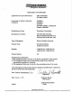
Engines & Generators Declaration of Conformity Application of Conncil Directive(s) EMC 89/336IEEC ISO 8846 1990(E) Standard(s) to Which Conformity is declared ENS0081-1 ENS0082-2 ENSS020 ISO-8846-1990(E), Certification Number, IWES003 Manufacturers Name Westerbeke Corporation Manufacturers Address 150 John Hancock Road Myles Standish Industrial Park Taunton, Ma. 02780-7319, USA Type of Equipment Marine Gasoline Generator Product Name Westerbeke Marine Gasoline Generator Model(s) 3.
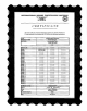
INTERNATIONAL MARINE CERTIFICATION INSTITUTE Rond Point SchulMn II, Box tI 8 - 1040 BRUXELLES BELGIQUE 1lI1: (32) 2-238-1892 fmc: (32) 2-2S8-770D CERTIFICATE We hereby certify the component stated below meets the EC Directive 94125/EC for EC type-examination in accordance with ISO 8846 and has following characteristics: TYPE MANUFACTURER ADDRESS GROUP OF Modell Model 2 Model 3 Model 4 ModelS ModelS Model 7 ModelS Model 9 Model 10 Model 11 Model 12 Model 13 Model 14 Model 15 ModellS Model 17 ModellS Mode
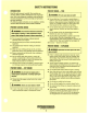
SAFETY INSTRUCTIONS INTRODUCTION PREVENT BURNS - FIRE Read this safety manual carefuUy. Most accidents are caused by failure to folJow fundamenJal rules and precautions. Know when dangerous condiJions exist and Iilke the necessary precautions to protect yourself, your personne4 and your machinery. The foUowing safety instructions are in compliance wiJh the American Boat and Yacht Council (ABYC) standards.
(
SAFETY INSTRUCTIONS ACCIDENTAL STARTING TOXIC EXHAUST GASES A WARNING: Accidental starting can cause injury A WARNING: Carbon monoxide (CO) is a deadly gas! orduth! • • • Ensure that the exhaust system is adequate to expel gases discharged from the engine. Cbeck the exhaust system regularly for leaks and make sure the exhaust manifolds are securely attached and no warping exists. Pay close anention to the manifold, water injection elbow, and exhaust pipe nipple.
(
SAFETY INSTRUCTIONS • • ABYMFPA AND USCG PUBLICATIONS FOR INST NG DlESa ENGINES Do not wear loose clothing or jewelry when servicing equipment; tie back long hair and avoid wearing loose jackets, shirts, sleeves, rings, necklaces or bracelets that could be caught in moving parts. Read the following ABYC, NFPA and USCG publications for safety codes and standards. Follow their recommendations when installing your engine. Make sure all attaching hardware is properly tightened.
(
INSTALLATION When installing WESTERBEKE engines and generators it is important that strict attention be paid to the following information: CODES AND REGULATIONS Strict federal regulations, ABYC guidelines, and safety codes must be complied with' when installing engines and generators in a marine environmenl SIPHON-BREAK For installations where the exhaust manifold/water injected exhaust elbow is close to or will be below the vessel's waterline, provisions must be made to install a siphonbreak in the raw
(
TABLE OF CONTENTS Parts Identification ................................................2 Introduction ............................................................. 3 Engine Adjustments ............................................ .26 Speed Hertz AdjustmenL ............................... 26 Torquing the Cylinder Head Bolts ................ 26 Spark Plugs ......... '" ......................................... 27 Drive Belt Adjustment... ................................. 27 Valve Clearance . '" .............
BCGB PARTS IDENTIFICATION AIR INTAKE ENGINE Oil Fill PRESSURE CAP WATER INJECTED EXHAUST ELBOW REMOTE PANEL CONNECTION CIRCUIT BREAKER COOLANT DRAIN GENERATOR BACKEND REAR Oil PAN LEFT SIDE 'HI,XI'" MOUNT CARBURETOR RIGHT SIDE HOURMETER ENGINE Oil Fill ~~3i\t----- RAW WATER CONTROL _---~::;;;::~:...
INTRODUCTION WESTERBEKE CANNOT BE RESPONSIBLE FOR THE CONTENT OF SUCH SOFTWARE, MAKES NO WARRANTIES OR REPRESENTATIONS WITH RESPECT THERETO, INCLUOING ACCURACY, TIMELINESS OR COMPLETENESS THEREOF ANO Will IN NO EVENT BE LIABLE FOR ANY TYPE OF OAMAGE OR INJURY INCURRED IN CONNECTION WITH OR ARISING OUT OF THE FURNISHING OR USE OF SUCH SOFTWARE.
INTRODUCTION ORDERING PARTS PROTECTING YOUR INVESTMENT Whenever replacement parts are needed, always provide the generator and engine model and serial numbers. In addition, include a complete part description and part number for each part needed (see the separately furnished Parts Catalog). Also insist upon WESTERBEKE packaged parts because will fit or generic parts are frequently not made to the same specifications as original equipment.
FUEL, ENGINE OIL AND ENGINE COOLANT GASOLINE ENGINE COOLANT Westerbeke recommends a mixture of 50% antifreeze and 50% distilled water, when possible. Distilled water is free from the chemicals that can corrode internal engine surlaces. A CAUTION: Only use unleaded fuel with an octane rating of 89 or higher. Leaded fuel will cause The antifreeze performs double duty, as it allows the engine to run at proper temperatures by transfening heat away from the engine to the coolant.
CONTROL PANELS GENERATOR CONTROL PANEL REMOTE PANEL The ON and START/STOP switches are the only functional There are three functional components on the remote panel for generator operation: components to operate the generator at the engine. Both switches are used to start the generator - see Starting the Generator under OPERATING INSTRUCTIONS. 1. ON switch The ON switch is a two-position switch with momentary contacts in the up (on) position and a stationary contact function in the center position.
PREPARATIONS FOR INITIAL START-UP PRESTART INSPECTION Before starting your generator for the first time or after a prolonged layoff, check the following items: • Check the engine oil level: add oil to maintain the level at the full mark on the dipstick. • Check the fuel supply and examine the fuel filter/separator bowls for contaminants. • Check the DC electrical system. Inspect wire connections and battery cable connections. • Check the coolant level in both the plastic recovery tank and at the manifold.
OPERATING INSTRUCTIONS GENERATOR CONTROL PANEL Starting the Generator To start the generator, hold the momentary ON switch in the up (on) position, then hold the momentary START/STOP switch in the up (start) position (both switches are held up together). After approximately one second, the starter will engage and the engine will crank. Once the engine is running, the starter will disengage, and the START/STOP switch may then be released to return to its center (run mode) position.
OPERATING INSTRUCTIONS REMOTE PANEL Starting the Generator To start the generator, hold the momentary ON switch in the up (on) position (the green light will come on), then hold the momentary START/STOP switch in the up (start) position (both switches are held up together). After approximately onc second. the starter will engage and the engine will crank {the green light will dim).
BREAK-IN PROCEDURE/DAILY OPERATION BREAK-IN PROCEDURE NOTE: Some unstable running may occur in a cold engine. This condition should abate as normal operating temperature is reached and loads are applied. After the generator has been started, check for proper operation and then encourage a fast warm-up. Run the generator between 20% to 60% of full load for the first 10 hours. A CAUTION: 00 not operate the generator for long A CAUTION: periods of time without a load being placed on the generator.
SAFETY SHUTDOWN SAFETY SHUTDOWN SWITCHES The engine is protected by a variety of shutdown switches. Should a shutdown occur, do not attempt to resfllrt without finding and correcting the cause. Refer to the heading Engine starts, runs and then shuts down in the ENGINE TROUBLESHOOTING section of this manual.
MAINTENANCE SCHEDULE A WARNING: Never attempt to perform any service while the engine is running. Wear the proper safety equipment such as goggles and gloves, and use the correct tools for each job. Disconnect the battery terminals when servicing any of the engine's DC electrical equipment. NOTE: Many of the follnwing maintenance procedures are simple but others are more difficult and may require the expen knowledge of a service mechanic.
MAINTENANCE SCHEDULE NOTE: Use the engine hounneter gauge to log your engine hours or record your engine hours by running time. SCHEDULED MAINTENANCE Heat Exchanger CHECK EACH DAY HOURS OF OPERATION 50 100 250 500 0 0 0 0 Raw Water Pump 0 0 Clean or replace anode. Open heat exchanger end cap and clean out debris. Remove every 1000 hours for professional cleaning and pressure testing. 0 Remove pump cover and inspect impeller for wear; replace if needed. Also replace gasket.
COOLING SYSTEM DESCRIPTION In other words, the engine is cooled by fresh water coolant, this coolant is cooled by raw water, and the raw water carries the transferred heat overboard through the exhaust system. The fresh water coolant and raw water circuits are independent of each other. Using only fresh water coolant within the engine allows the cooling water passages to stay clean and free from harmful deposits. Westerbeke marine engines are designed and equipped for fresh water cooling.
COOLING SYSTEM FRESH WATER COOLING CIRCUIT CHANGING COOLANT NOTE: Refer to the ENGINE COOLANT section for the recommended antifreeze and water mixture to be used as the fresh water coolant. The engine's coolant must be changed according to the MAINTENANCE SCHEDULE. If the coolant is allowed to become contaminated, it can lead to overheating problems. Fresh water coolant is pumped through the engine by a circulating pump, absorbing heat from the engine.
COOLING SYSTEM If the zinc anodes need replacement, hold the hex boss into THERMOSTAT which the zinc anode is threaded with a wrench while loosening the anode with another wrench. This prevents the hex boss from possibly tearing off the exchanger shell. After removing the zinc, note the condition of it. If the zinc is in A thermostat controls the coolant temperature as the coolant continuously flows through the closed cooling circuit.
COOLING SYSTEM RAW WATER INTAKE STRAINER RAW WATER PUMP NOTE: Always install the strainer at or below the waterline so The raw water pump is a self-priming, rotary pump with a non· ferrous housing and a Neoprene impeller. The impeller has flexible blades which wipe against a curved carn plate within the impeller housing, producing the pumping action. On no account should this pump be run dry. There should always be a spare impeller and impeller cover gasket aboard (an impeller kit).
FUEL SYSTEM GASOLINE Use unleaded 89 octane or higher gasoline. When fueling, follow U.S. Coast Guard regulations, close off all hatches and companionways to prevent fumes from entering the boat, and ventilate after fueling. A WARNING: Fuel leakage at the fuel pump or its connections is a fire hazard and should be corrected. Make sure proper ventilation exists whenever servicing fuel system components.
CARBURETOR ADJUSTMENTS CARBURETOR Carburetor Filter Screen The carburetor is a single barrel, down-draft type with a cleanable metal screen air intake filter/spark arrester. Clean this filter element after the first 50 hours of operation, then clean and inspect every 250 operating hours. Replace the screen if necessary. Tighten the plug and make certain there are no leaks. The choke is operated by a 12 VDC solenoid. TIris choke solenoid is activated when the ON switch is depressed and stays activated.
ENGINE LUBRICATING OIL DESCRIPTION A WARNING: Used engine oil contains hannful contaminants. Avoid prolonged skin contact. Clean skin and nails thoroughly using soap and water. Launder or discard clothing or rags containing used oil. Discard used oil properly. Use a heavy duty engine oil with an API classification of SJ. Change the engine oil after an initial 50 hours of break-in operation and every 100 hours of operation thereafter.
OIL PRESSURE NOTE: WESTERBEKE recommends that the following engine adjustments be peifonned by a competent engine mechanic. The infonnation below is provided to assist the mechanic. DESCRIPTION LOW OIL PRESSURE The lubricating system is a pressure feeding system using an oil pump. The engine oil is drawn from the oil sump by the oil pump, which drives the oil, under pressure, through the oil filter, oil cooler and various lubricating points in the engine.
REMOTE OIL FILTER (OPTIONAL) INSTALLATION To install, simply remove the engine oil filter and thread on WESTERBEKE's remote oil filter kit as shown. Always install this kit with the oil filter facing down as illustrated. This popular accessory is used to relocate the engine's oil filter from the engine to a more convenient location such as an engine room bulkhead. Contact your WESTERBEKE dealer for more information.
-- ..... 4.5KW /7.0KW BeGB GENERATOR WIRING DIAGRAM #43864 . ;; i.16 VIO/WIIT '14 RH '=l;;:m ...... 416 8Lk ~ '----+-t-----t-H-t-H-t-t---"-'-'''''---*--jll' tl' R£lHYIO I J I '---'!. "" ~I R " '-"fN'IWESTERBEKE I Engines & Generators 23 / '".
4.SKW /7 .OKW BeGB GENERATOR WIRING SCHEMATIC #43864 J - 12 VDC r : BATTERY , SWITCH 1 1... STARTER SOLENOID 1 1 1 1 1 1 ..... r: t-I '20 AMP ( I CIRCUIT ~I BREAKER 'Kj"Jt1 ..." ( r • 1 '""I r I I I 1 I I __ ... BAmu fUEL PUNP (HAUER ~ " .. STOP SW , 1... STARTER r--l I eKllotC) I I I I fUEL SOL. HOUR METER COil "~\,, , ~ 1 L..----- 1 , I I 1 1 1 1 o. f.-wrrc» L~J 'T~T , l . .. DIODE CHOIE SOL. .
REMOTE PANEL WIRING SCHEMATIC #043912 REMOTE PANEL RED RED CKT I ' - - - - - - - t - - - i \ ' I ON SW WHITE WHITE *14 RED/VIO VIEWED FROM MATING END Engines & Generators 25
ENGINE ADJUSTMENTS NOTE: WESTERBEKE recommends that the following engine adjustments be peifonned by a competent engine mechanic. The information below is provided to assist the mechanic. ENGINE SPEED (HERTZ) ADJUSTMENT Governor Maintenance Governor 1. Periodically lubricate the linkage arm attaching points at the governor arm and throttle lever. Use a graphite lubricant or equivalent. The belt-driven, mechanically operated governor maintains the engine's rpm under various load conditions.
ENGINE ADJUSTMENTS SPARK PLUGS DRIVE BELT ADJUSTMENT The spark plugs should be cleaned and regapped after the fIrst 50 hour break-in period, then inspected every 250 hours thereafter and replaced as needed. The drive belt must be properly tensioned. Excessive drive belt tension can cause rapid wear of the belt and reduce the service life of the fresh water pump's bearing. A slack belt or the presence of oil on the belt can cause belt slipping, resulting in high operating temperatures.
ENGINE ADJUSTMENTS NOTE: WESTERBEKE recommends that the following engine adjustments be peiformed by a competent engine mechanic. The injonnation below is provided to assist the mechanic. VALVE CLEARANCE ADJUSTMENT IGNITION TIMING NOTE: Retorque the cylinder head bolts before adjusting the 1. Attach a timing light to the #1 spark plug and mark the front timing pointer to indicate 1'5°. Locate the timing mark on the crankshaft pulley and mark it with white chalk or a crayon.
ENGINE ADJUSTMENTS NOTE: WESTERBEKE recommends that the following engine adjustments be peiformed by a competent engine mechanic. The infonnation below is provided to assist the mechanic. TIMING BELT INSPECTION AND REPLACEMENT 5. Remove the timing belt. NOTE: If the timing belt is to be reused, draw an arrow on the belt back to indicate the direction of rotation (clockwise). Timing Belt Removal A CAUTION: Water Dr oil on the timing belt severely reduces the service life of the belt.
ENGINE ADJUSTMENTS NOTE: WESTERBEKE recommends that the following engine adjustments be performed by a competent engine mechanic. The information below is provided to assist the mechanic. Crankshaft Bolt Removal Flange Installation 1. Lock the crankshaft in position. 1. Mount the flange so that its side shown by the heavy arrow in the illustration faces toward the sprocket. NOTE: Do not tum the crankshaft. FLANGE 2. Remove the crankshaft bolt.
ENGINE ADJUSTMENTS NOTE: WESTERBEKE recommends that the following engine adjustments be performed by a competent engine mechanic. The injonnation below is provided to assist the mechanic. Tensioner Spring/Timing Tensioner Installation At this time, check that the moveable range of teeth on the oil pump sprocket is according to specifications. 1. Install the tensioner spring and timing belt tensioner. Standard value: 4 to 5 teeth in forward direction. 1 to 2 teeth in reverse direction. 2.
ENGINE ADJUSTMENTS NOTE: WESTERBEKE recommends that the following engine adjustments be peiformed by a competent engine mechanic. The information below is provided to assist the mechanic. 8. Tum the crankshaft clockwise by nine camshaft sprocket teeth (817) to align the timing mark on the camshaft sprocket with the tensioner set mark on the timing belt ENGINE COMPRESSION TEST 1. To check the engine's compression pressure, warm up the engine then shut it down. rear cover. A 2.
COMPONENT TESTING NOTE: WESTERBEKE recommends that the following engine testing adjustments be perjonned by a competent technician. GENERAL All DC voltage measurements are made to the engine battery negative ground point unless specified otherwise. In making test measurements, make sure that a good ground for the meter is established, preferably the point where the negative battery is connected to the engine. Battery positive voltage is indicated as B+ and should measure no less than JI.5 volts.
ENGINE TROUBLESHOOTING The following troubleshooting tables are based upon certain engine problem indicators and the most likely causes of the problems. NOTE: The engines control system (electrical system) is protected by a 20 Ampere manual reset circuit breaker located on the control panel. When troubleshooting indicates an electrical problem, see the ELECTRICAL SYSTEM WIRING DIAGRAM, as these may reveal other possible causes of the problem which are not listed below. Engine does not crank.
ENGINE TROUBLESHOOTING PROBLEM Engine misfires. PROBABLE CAUSE PROBLEM No DC charge to the starting battery. 1. Poor quality fuel. 2. 3. 4. 5. 6. Incorrect timing. Dirty flame arrester. Cracked distributor cap. Faulty ignition wires. Spark plugs are worn. 7. High exhaust back-pressure. 8. Valve clearances are incorrect. Engine backfires. Blue exhaust smoke 1. Lube oil is diluted. discharge from the engine. 2. High lube oil level. 3. Crankcase breather hose is clogged. 4.
GENERATOR INFORMATION USE OF ELECTRIC MOTORS Generator Frequency Adjustment The power required to start an electric motor is considerably more than is required to keep it running after it is started. Some motors require much more current to start them than others. Split-phase (AC) motors require more current to start, under similar circumstances, than other types.
Be GENERATOR SINGLE PHASE NOTE: WESTERBEKE recommends that the following generator tests and adjustments be peiformed by a qualified technician. DESCRIPTION Circuit Breaker The Be generator is a brushless, self-excited generator which requires only the driving force of the engine to produce an AC output. The stator houses t:'IXro setS of windings; the main stator windings and the exciter windings.
Be GENERATOR SINGLE PHASE NOTE: WESTERBEKE recommends that the following generator tests and be peiformed by a qualified technician. GROUND SINGLE EXCITER CIRCUIT BRIDGE 60Hz 120 VOLT CONFIGURATION ILLUSTRATION CAPACITOR/ WHITE NOTE: THE #7 WIRE IS SHOWN CONNECTED AS A DEMONSTRATION OF HOW THESE CONNECTIONSCAN BE MADE. , -
Be GENERATOR SINGLE PHASE NOTE: WESTERBEKE recommends that the following generator tests and adjustments be performed by a qualified technician. DUAL EXCITER CIRCUIT 60 Hz 120 VOLT CONFIGURATION ILLUSTRATION >. 50Hz LEAD / , INTEGRAL CONTROLLER [BATTERY CHARGER! '- ,fi~if"·./ ...... -;./ ~ ..... --) , / TERMINAL BOARD II DUAL EXCITER CIRCUIT MODEL These generators have dual Hertz and no-load voltage adjustment connectors at each capacitor.
AC TERMINAL BOARD CONNECTIONS ACTERMINAL L1 N L1 ((W.@£3) @ ® ® @ BLACK BREAKER 120V/60Hz 230V/50Hz L1 115V/50Hz • • L1 N N L1 BATTERY CIRCUITS I RESISTANCE VALUES MODEL 4.5 r·O----;;AM,---------------------------------l ,," ,, fr----: n: , r---------, I : " I iDloofrl ! - r I II Bl ::.:1 lA I: 2~1 I ::::1 I I i ! r J I II II I DIODE r I I L_________ : I I 98 CAPACITOR RATINGS 4.5 BC 7.0 BC 25MF 31.
Be GENERATOR SINGLE PHASE TESTING THE EXCITER WINDINGS Single Capacitor 1.9 Ohms 3. With an ohmmeter set on the high R scale, place its plus (+) lead on one capacitor connection and the negative (-) lead on the other capacitor connection. A resistance should be read and should rise slowly as the meter attempts to charge the capacitor. This indicates a presumably good capacitor. Dual Exciter 2.2 Ohms An AC voltage is induced in these windings by the rotating field.
Be GENERATOR SINGLE PHASE Testing Component Resistance Values 2. Diodes 8 - 9.5 ohms (approximate) using a 260 Simpson Analog Meter To check the diode, unsolder the connection from the top of the diode. Place one ohmmeter lead on the connection at the top of the diode and the other ohmmeter lead to the diode's base. Then reverse the position of the ohmmeter leads. Rotating Field/Auxiliary Windings and Diodes Two sets of windings are found in the rotor assembly.
Be GENERATOR SINGLE PHASE INTEGRAL CONTROLLER (I.C.) Testing the Battery Charging Circuit The Integral Controller (I.C.) is an encapsulated, solid-state unit that supplies a DC charging voltage to the generator's starting battery while the generator is opening. 1. Bridge Rectifier Normal AC voltage running to the rectifier (while the engine is operating at 1800 rpm) is measured across the two AC connections on the bridge rectifier. (As illustrated). Charging Voltage: 13.0 - 14.
BATTERY CHARGING CIRCUIT The DC Circuit on the BCGB functions to start, operate and stop the generator's engine. The circuit is best understood by reviewing the DC Wiring Diagram and Wiring Schematic. The engine's DC wiring is designed with three simple basic circuits: start, run and stop. The engine has a 12 volt DC electrical control circuit that is shown on the Wtring Diagrams. Refer to these diagrams when troubleshooting or when servicing the DC electrical system or the engine.
TESTING THE BATTERY CHARGING CIRCUIT BATTERY CHARGER The generator supplies a continuous 17 amp charge from its battery charger to the starting battery. To test the battery charger put a multimeter between the positive (+) and negative (-) leads to the battery. It should indicate 13.5V to 14V with the engine running. If only the battery voltage is indicated, check that the battery charger tenninal connections are tight. With the unit running, test between the (+) and (-) tenninals for 13.5V to 14Y.
SHORE POWER TRANSFER SWITCH 120 VOLT/50 HERTZ TWO WIRE CONFIGURATION Generator 230 VOLT/50 HERTZ TWO WIRE CONFIGURATION NOTE: Diagram shows connections for a two- ~ wire. 120-Volt system from the generator. with three_wire,120_Volt boat system. ~ L1 4 o5 3 0 6 2 N PN 32009 Ship·lo·Shore Switch 13 Pole) PH 32008 (40Amps/Pole) ;; ~ .'----~} /-', ~\-+-~N"'e"e!""'a'-'_N -r;l.....,,/ j -.
LAY-UP & RECOMMISSIONING General Fuel System [Gasoline] Many owners rely on their boatyards to prepare their craft, Top off your fuel tanks with unleaded gasoline of 89 octane or higher. A fuel conditioner such as STABIL gasoline stabilizer should be added. Change the element in your gasoline/water separator and clean the metal bowl. Re-install and make certain there are no leaks. Clean up any spilled fuel.
LAY-UP & RECOMMISSIONING Starter Motor Spare Parts Lubrication and cleaning of the starter drive pinion is advisable, if access to the starter permits its removal. Make sure the battery connections are shut off before attempting to remove the starter. Take care in properly replacing any electrical Lay-up time provides a good opportunity to inspect your WESTERBEKE engine to see if external items such as drive belts or coolant hoses need replacement.
GENERATOR SPECIFICATIONS ENGINE SPECIFICATIONS Engine Type 3 cylinde~ 4 cycle, overhead camshaft w/counterbalance shaft, carbureted water cooled gasoline engine Bore & Stroke 2.56 x 2.61 inches (65.0 x 66.3 mm. General Total Displacement 40.3 cubic inches (.66 liter) Bearings Four main bearings Combustion Chamber Semi-spherical Compression Ratio 9.
STANDARD HARDWARE BOLT HEAD MARKINGS 80lt strength classes are embossed on the head of each bolt. Customary (inch) bolls are identifed by markings two to grade eight (strongest). The marks correspond to two marks less than the actual grade, Le.; a grade seven bolt will display five embossed marks. rade2 Metric bolt class numbers identify bolts by their strength with 10.9 the strongest. ~rade5~ra. de7 • GradeS ~"."" ~ 3>P~ ""Ii,;:: U '" I" NOTES: 1.
BeGB GENERATOR HARDWARE TORQUES liming Belt Crankshaft bolt Timing belt cover bolts Nm ft.lbs. 135-145 98-105 10-12 7-9 Nm ft. Ibs.
METRIC CONVERSIONS MILLIMETERS TO INCHES INCHES TO MILLIMETERS Inches mm 1 2 3 4 5 10 25.40 50.80 76.20 101.60 127.00 254.00 mm Inches 15 20 25 30 35 40 381.00 508.00 635.00 762.00 889.00 1016.00 mm Inches mm Inches 1 2 3 4 5 10 0.0394 0.0787 0.1181 0.1575 0.1969 0.3937 15 20 25 30 35 40 0.5906 0.7874 0.9843 1.1811 1.3780 1.5748 10 MIlliMETERS = 1 CENTIMETER, 100 CENTIMETERS = 1 METER = 39.37 INCHES (3.3 FEET) INCHES TO METERS Inches Meters 1 2 3 4 5 6 7 8 9 10 11 12 0.0254 0.0508 0.
SUGGESTED SPARE PARTS WESTERBEKE MARINE GASOLINE GENERATORS CONTACT YOUR WESTERBEKE DEALER FOR SUGGESTIONS AND ADDITIONAL INFORMATION DISTRIBUTER CAP WITH WIRES FUEL LIFT PUMP SPARE FUSES SPARE PARTS KIT - - - - - - WESTERBEKE offers two Spare Parts Kits, each packaged in a rugged hinged toolbox. Kit A includes the basic spares. Kit B is for more extensive off-shore cruising.
~ WESIERBEKE Engines & Generators