
Installation manual


GENERAL
COMPONENT
TESTING
NOTE:
WESTERBEKE recommends that the following engine
testing adjustments be perjonned by a competent technician.
TAP
THE
GROUND
CONNECTION
TO
THE
TERMINAL
All
DC
voltage
measurements
are
made
to
the
engine
battery
negative
ground
point
unless
specified
otherwise.
In
making
test
measurements,
make
sure
that
a
good
ground
for
the
meter
is
established, preferably the point where the negative
battery
is
connected
to
the
engine.
Battery
positive voltage
is
indicated
as
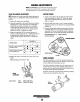
B+ and should measure no less than JI.5 volts.
o
RELAY
SHOULD
___
~o~o
"CLICK"
ON.
AC
voltage measurements should
be
made
with a
true
RMS
AC
meter
to
insure measurement accuracy.
GROUND
AND
8(+)
CONNECTIONS
---
.•
",.
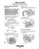
RELAYS
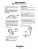
The relays used in the control system have coils which are
polarized by the fact that they have internal free wheeling
suppression diodes across them. Relay coil terminal 86 must
be maintained
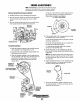
(+), terminal 85(-). The relay coil
is
rated 12V
DC, and the coil resistance
is
typically
85
ohms. With
B+
on
tenninal
86,
direct
grounding
of
tenninal
85
is
pennissible
for
testing
purposes.
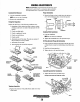
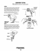
RELAYS
RELAY
TERMINALS
REMOVE
THIS
RELAY
CONNECTOR
~
WESTERBEKE
Engines & Generators
33
TO
B(+)
TESTING
THE
RELAY
TERMINALS
TESTING
COIL
RESISTANCE