
Installation manual


Be
GENERATOR
SINGLE
PHASE
NOTE:
WESTERBEKE recommends that the following generator tests
and be peiformed by a qualified technician.
NOTE:
THE
#7
WIRE
IS
SHOWN
CONNECTED
AS
A
DEMONSTRATION
OF
HOW
THESE
CONNEC-
TIONSCAN
BE
MADE.
GROUND
BRIDGE
CAPACITOR/
SINGLE
EXCITER
NO-LOAD
VOLTAGE
ADJUSTMENT
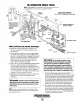
1.
Remove the louvered metal plate, at the back
of
the
generator,
covering
the
AC
terminal
connections
and
the capacitor(s).
2.
Start the generator and allow it to run for approximately
five
minutes
so
the
engine
can
wann
up.
Make
Sure
the
generator
is
operating
without
any
equipment
drawing
AC
current
from
the
generator
(that
is,
shut
off
all
electrical
appliances). Make sure the engine's speed (Hertz)
is
correct. Adjust the governor
as
needed
to
obtain the
correct
engine
speed
before
proceeding.
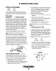
3. Refer to the AC LOAD CONNECTIONS DIAGRAM for
the
correct
configuration
then
check
the
generator's
no-load
voltage
by
measuring
the
voltage
across
the
neu-
trallead and the hot lead with a volt meter. Make sure you
record
this
reading.
The
generator's
no-load voltage
is
115
- 124 volts at 60.5 - 61.5 Hertz.
If
the voltage output
is
higher
or
lower
than
specified, proceed.
4.
Shut
off
the generator. Make sure the correct Hertz lead
(60 Hertz #6, or 50 Hertz #5)
is
plugged into the
capacitor(s).
A
WARNING:
Capacitors
must
be
discharged
before
handling
as
they
store
electricity
and
can
pack
a
poten-
tially
lethal
charge
even
when
disconnected
from
their
power
source.
NOTE:
Simply cross the capacitor's two terminals with an
insulated (plastic handle) screwdriver. This will discharge
any excess electricity.
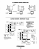
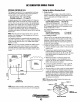
SINGLE
EXCITER
CIRCUIT
60Hz
120
VOLT
CONFIGURATION
ILLUSTRATION
WHITE
,
-<b"-INTEGRAL
CONTROLLER
//
[BATTERY
CHARGERI
TERMINAL
BOARD
II
lz
A
WARNING:
00
not
attempt
to
make
a
no-load
voltage
adjustment
while
the
generator
is
operating.
The
capacitor
can
produce
a
400-500
volt
charge.
Touching
any
wiring
can
produce
a
severe
electrical
shock.
In
addition,
attempting
to
make
a
no-load
volt-
age
adjustment
while
the
generator
is
operating
could
cause
your
fingers
to
be
caught
in
the
generator's
rotor.
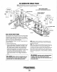
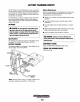
5.
There
are
three
plugs
grouped
for
the
capacitor
tenninal, #7, #8,
and
#9.
If
the
generator's
no-load voltage
is
low,
then
disconnect
the
lower
numbered
plug
and
con-
nect
the
plug
with
the
next
higher
number.
If
the
genera-
tor's no-load voltage
is
high, then disconnect the higher
numbered
plug
and
connect
the
plug
with
the
next
lower
number. Note that the plug presently connected
to
this
terminal may be
anyone
of
the three plugs available.
6.
If
the
generator's
no-load voltage
cannot
be
adjusted
because the voltage needs
to
be increased and the highest
numbered
plug
is
already
connected
to
the
right
tenninal,
or
the
voltage
needs
to
be
lowered
and
the
lowest
num-
bered plug
is
connected, refer to the WESTERBEKE BC
Generator
Troubleshooting
Guide),
Engines & Generators
38