
Installation manual


Be
GENERATOR
SINGLE
PHASE
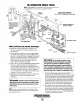
Testing
Component
Resistance
Values
Rotating
Field/Auxiliary
Windings
and
Diodes
Two
sets of windings
are
found
in
the
rotor
assembly.
An
AC
voltage is
produced
in
two
groups
of windings
as
the
rotor
turns at rated rpm. The
AC
voltage passes through each
of
the two diodes mounted on the isolated fixture just before the
rotor
carrier
bearing.
The
AC
sine
wave
is
changed
to
a
DC
and
this
DC
voltage
is
passed
through
the
two
groups
of
rotating field windings producing a DC field around these
windings. This field affects the AC winding
of.
the two main
stator
groups
inducing
an
AC
voltage
in
these
windings
that
is
available at the AC terminal block connections.
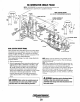
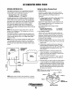
DIODE
1.
Rotating Field! Auxiliary Windings
Single Capacitor 3.8 Ohm - Dual Excitor _ 4.0 Ohm
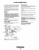
To
check
the
resistance
values,
rotate
the
engine's
crank-
shaft to position the diode(s) on the generator's shaft at
12
0'
clock. To make a quick check
of
these windings,
presume the diode is
OK
and place one
of
the ohmme-
ter's leads on the connection at the top
of
the diode and
the other lead at the connection at the base
of
the diode.
Compare readings with the value above.
If
a distinct dif-
ference is noted in the ohm value, carefully unsolder the
lead
on
the top
of
the diode and remove the diode from
its isolated heat sink using a thin walled, deep well
7116
in
(II
mm) socket.
NOTE:
The
aluminum heat sink that the diode threads into
can be bent carefully outboard
to
make easier access
to
the
diode.
With the diode removed, both leads for the first group
of
rotating
field/auxiliary
windings
will
be
isolated
with
no
interference from a possibly faulty diode.
Check the resistance value
of
the rotating windings by
placing the ohmmeter's leads across the two exposed
leads.
Also,
verify
that
no
continuity exists between these wind-
ings
and
the
rotor
shaft
by
leaving one
ohmmeter
lead
attached to the winding lead and the other ohmmeter lead
touching the shaft: no continuity should exist.
If
continu-
ity is found, a short exists
..
Repeat this same check on the second group
of
windings.
Rotate the engine's crankshaft
180
0
to
position the sec-
ond diode and connections at
12
o'clock.
No continuity should
be
found between these two groups
of
windings.
2. Diodes 8 - 9.5 ohms (approximate) using a 260 Simpson
Analog Meter
To check the diode, unsolder the connection from the top
of
the
diode. Place one
ohmmeter
lead
on
the
connection
at the top
of
the diode and the other ohmmeter lead to the
diode's base. Then reverse the position
of
the ohmmeter
leads.
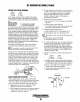
DIODE
H
(+)
LOW
RESISTANCE
A low resistance should be found with the leads in one
direction, and infinite resistance (blocking) in the other
direction. Different
meters
will
read
different
resistance
values through the diode.
NOTE:
Different meter models may show different
ohm
values, but should read
the
same for both
diodes.
Diode Rating: 1600 amps 26 Amps
The
diode's
rating
is
far
in
excess
of
the
circuit's
require-
ments. Most likely a diode failure will result from an
overspeed
or
load
surge.
Main
Stator
Windings
Single
Capacitor
0.6 Ohms
Dual
Excitor
0.5 Ohms
Residual voltage measured between # 1-#3 and #4-#6 will be
2-3 volts AC between each pair
of
leads at the terntinal
block. This would be an indication that the stator windings
are okay. Check exciter windings and artificially excite the
generator.
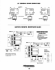
NOTE:
THE
NUMBERED
LEADS
ON
THE
TERMINAL
BLOCK
ARE
NOT
IN
ANY
NUMERICAL
ORDER.
THEY
ARE
AS
SHOWN
BELOW
, , 3
000
, 2 6
000
TERMIIIIALliLD.C.K
Group #1 - Measure resistance value betw.een terntinal with
lead #1 and terntinal with lead #3. (Check that there
is
no
continuity
of
Group
#1
windings to the case ground.)
Group #2 - Measure resistance value between terntinal with
lead
#4
and terminal with lead #6. (Check that there is no
continuity of
Group
#2 windings
to
the
case
ground.)
Check for a possible short between the two groups
of
stator
windings by placing one lead
of
the ohmmeter on the ternti-
nal with the stator lead #3 and the other ohmmeter lead on
the terntinal with stator lead #6. There should be
no
continu-
ity
between
the
two
groups
of
stator
windings.
Engines
&
Generators
42