
Installation manual


o
'"
,.
z
'"
m
Be
GENERATOR
SINGLE
PHASE
INTEGRAL
CONTROLLER
(I.C.)
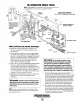
The
Integral Controller (I.C.) is an encapsulated, solid-state
unit that supplies a
DC
charging voltage to the generator's
starting battery while the generator is opening.
Charging
Voltage: 13.0 - 14.0 volts
DC
Charging
Amperage:
0 - 17.0
amps
DC
A separate
group
of stator windings supplies
AC
voltage to a
bridge rectifier which converts the
AC
current to supply the
I.e.
unit. The
I.e.
unit senses
the
needs
of
the starting battery
and supplies a DC charge when
one
is needed.
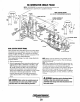
If
you suspect
that the I.C. unit is faulty (that is,
if
the battery's charge is
low), check the charging circuit and it's components as
described in the following steps. Check all connections for
cleanliness and tightness including the ground before replacing
the I.C. unit.
NOTE:
When
the
generator is first started, the
I.
C.
unit will
produce a
low
charging
rate.
This charging rate will
n'se
as
the generator
is
operated.
The Integral Controller is mounted inside the generator hous-
ing in the
12:00
position. There is a voltage output adjustment
on the controller that will allow a
DC
voltage output adjust-
ment
of
± 2 volts.
NOTE:
New four wire controllers eliminate the ballast resistor
circuit since
the
ballast resistor's function is now handled
internally. Whenever replacing
an
early stylr controller with
the
newer four wire model,
rerrwve
the ballast resistor and its
wiring.
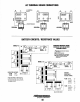
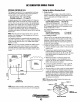
INTEGRAL
CONTROLLER
VOLT
~
+ _
GND
o
BLACK
VOLTAGE
OUTPUT
ADJUSTMENT
(ON
BACK)'
_..J1'-I
+
AC
YELLOW
GROUND
TO
GENERATOR
CASE
BRIDGE
RECTIFIER
NOTE:
Earlier model controllers had white/green
(-)
negative
and whitelblack ground connections that
are
interchangeable.
AC
Testing
the
Battery
Charging
Circuit
1.
Bridge
Rectifier
Normal
AC
voltage running to the rectifier (while the
engine is operating at
1800 rpm) is measured across the
two
AC connections on the bridge rectifier. (As
illustrated).
AC voltage running to the bridge rectifier (approximate):
No-load
off
the
generator
16.0 volts
AC
Full-load
off
the
generator
17.5 volts
AC
Normal
DC
voltage running out
of
the rectifier (in volts
DC) is measured across the two
DC
connections
of
the
bridge rectifier; that is
+ and
-.
DC
voltage running from the bridge rectifier
(approximate):
No-load
off
the
generator
Full-load
off
the
generator
2.
AC
winding:
0.10
ohm
17.0 volts
DC
18.5 volts
DC
Lift the two
AC
wire leads off the bridge rectifier and
measure, the resistance between these two leads with an
ohmmeter.
It
should measure 0.10 ohm.
No
continuity
should exist between these two leads and the ground
Or
the main AC stator windings.
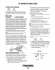
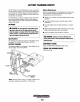
3. Testing
the
Bridge
Rectifier
(meter used - Simpson 260)
a.
Set your ohmmeter's scale on
RXI
(+ DC) and set the
needle to zero.
b. Connect the (+) positive lead from the ohmmeter to
point #4. Taking the ohmmeter's negative
H lead,
momentarily touch points #1, #2, #3, and #5.
The
ohm-
meter should register no deflection for any
of
the
points touched.
c. Remove the positive (+) lead from point
#4
and
connect
the
negative
(-)
lead; momentarily touch
points
#1, #2, and #3.
The
ohmmeter's needle should
deflect when each point is touched.
d.
Leaving the negative ohmmeter
(-)
lead on point #4,
. touch point #5 with the positive lead. No deflection
should take place.
e.
Place the positive (+) lead
On
point
#1
and the negative
(-)
lead on point #3.
The
ohmmeter again should no!
register any deflection (no deflection indicated infinite
resistance). Reverse these connections and the ohmme-
ter should again register no deflection.
If
the rectifier
fails any
of
the previous tests (A-E), replace the recti-
fier because it is defective.
NOTE:
Different types and/or brands
of
test meters may
produce opposite test
results.
POINT
#4
POINT
#3
POINT
15
MOUNTING
HOLE
~
WESTERBEKE
Engines & Generators
43