
Installation manual


BATTERY
CHARGING
CIRCUIT
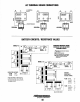
The DC Circuit on the BCGB functions to start, operate and
stop
the
generator's
engine.
The
circuit
is
best
understood
by
reviewing
the
DC
Wiring
Diagram
and
Wiring
Schematic.
The engine's DC wiring
is
designed with three simple basic
circuits: start, run and stop.
The engine has a 12 volt
DC electrical control circuit that
is
shown on the Wtring Diagrams. Refer to these diagrams
when troubleshooting or when servicing the
DC electrical
system
or
the
engine.
BATTERIES
A
CAUTION:
To
avoid
damage
to
the
battery
charg-
ing
circut,
never
shut
off
the
engine
battery
switch
while
the
engine
is
running.
Shut
off
the
engine
battery
switch,
however,
to
avoid
electrical
shorts
when
work-
ing
on
the
engine's
electrical
circuit.
Specifications
The minimum recommended capacity
of
the battery used in
the engine's 12-volt
DC
control circuit is 300 CCA.
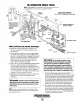
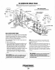
BATTERY
CHARGING
The generator supplies a continuous
17
amp charge from its
battery charger to the starting battery.
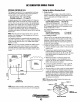
'iNTEGRAL
_______
y/
;;t.0NTROllER"
//"'-----.
~//
I
~~~
YEllOW
(+)
RED
TO
CIRCUIT
,
BREAKER
NOTE:
Should the battery charger
or
bridge rectifier fail, the
generator windings are protected
by
a
30
amp fuse.
Battery
Maintenance
Review
the
manufacturer's
recommendations
and
then
estab-
lish a systematic
maintenance
schedule
for
your
engine's
starting batteries and house batteries.
•
Monitor
your
voltmeter
for
proper
charging
during
engine
operation.
• Check the electrolyte level and specific gravity with a
hydrometer.
• Use only distilled water
to
bring electrolytes to a proper
level.
• Make certain that battery cable connections are clean and
tight to the battery posts (and to your engine).
• Keep your batteries clean and free
of
corrosion.
A
WARNING:
Sulfuric
acid
in
lead
batteries
can
cause
severe
burns
on
skin
and
damage
clothing.
Wear
protective
gear.
COMPONENT
TESTING
Refer to COMPONENT TESTING in this section.
TESTING
THE
CHARGING
CIRCUIT
See the next page.
Engines & Generators
44