
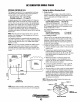
Installation manual


SHORE
POWER
TRANSFER
SWITCH
120
VOLT/50
HERTZ
TWO
WIRE
CONFIGURATION
230
VOLT/50
HERTZ
TWO
WIRE
CONFIGURATION
Generator
~
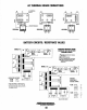
NOTE:
Diagram
shows
connections
for
a
two-
wire.
120-Volt
system
from
the
generator.
with
three_wire,120_Volt
boat
system.
;;
Ship·lo·Shore
Switch
13
Pole)
PH
32008
~
~\-+-~N"'e"e!""'a'-'
_N
Ships Load
(40Amps/Pole)
PN
32009
(80Amps/Pole)
PN
32010
(125
Ampsl
Pole)
PN
32133
(200Amps/Pole)
L1
z
w
w
'"
'"
~
4 3
o 0
5 2
GENERATOR
GROUND
N
6
'"
~
GENERATOR/SHORE
...I SWITCH
•
PN
32009
PH
32010
PH
32133
/-',
.'----~}
-r;l
.....
,,/
(WHT)
:~~~:O-VOlt
j -.G-;ound II'
Equipment
SHIP'S
LOAD
Z
(GRN)
,
~
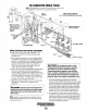
Shore
Power
If
the
installer connects shore power to the vessel's AC
circuit, this must
be
done
by
means of
the
Shore Power
Transfer Switch
..
Set
the
transfer switch shown
in
the
diagrams
to
the
OFF position. This switch prevents
simultaneous connection of shore power to generator output.
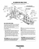
A
CAUTION:
Damage
to
the
generator
can
result
if
utility
shore
power
and
generator
output
are
connected
at
the
same
time.
This
type
of
generator
damage
is not
covered
under
the
warranty;
it
is
the
installer's
responsi-
bility
to
make
sure
all
AC
connections
are
correct.
\
L1
N )
SHORE POWER
230V
50HZ
-:;-
SHORE
GROUND
• N
_
SHIP'S
-
GROUND
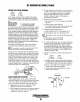
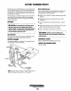
Switching
Shore
Power
to
Generator
Power
A
CAUTION:
Heavy
motor
leads
should
be
shut
off
before
switching
shore
power
to
generator
power
or
vice-versa
because
voltage
surges
induced
by
switching
with
heavy
AC
loads
on
the
vessel
being
operated
may
cause
damage
to
the
exciter circuit
components
in
the
generator.
Engines & Generators
46
I