OPERATOR'S MANUAL WESTERBEKE 4.5 KW BeG MARINE GASOLINE GENERATOR SET Publication #037491 Edition 1 November 1988 /-vtT' WESTERBEKE " WESTERBEKE CORPORA TlON • A VON INDUSTRIAL PARK, A VON, MA 02322.
Gasoline with an ETHANOL content higher than 10% (E10) is not allowed and may void warranty.
SAFETY PRECAUTIONS The following symbols appear in this manual to call attention to and emphasize conditions potentially dangerous to the • operator. Use Extreme Care When Handling Engine Euel (A constant danger of explosion or fire exists) Do not fill fuel tank(s) while the engine is running. Do not smoke or use an open flame near the engine orthe fuel tank. iWARNINGJ The above symbol is used in the manual to warn of possible serious personal injury or loss of life.
IMPORTANT PRODUCT SOFTWARE DISCLAIMER Product software of all kinds, such as brochures, drawings, technical data, operator's and workshop manuals, parts lists and parts price lists, and other information, instructions and specifications provided from sources other than Westerbeke, is not within Westerbeke's control and, accordingly, is provided to Westerbeke customers only as a courtesy and service.
FOREWORD Thank you for selecting a Westerbeke marine product for your use. We at Westerbeke are pleased to have you as a customer. Read this manual carefully and observe all safety precautions included throughout.
TABLE OF CONTENTS Section ......................................................................... Page GENERAL ........................................................................... 5 4.5 K:N BCG GENERAL SPECiFiCATIONS ....................... 8 4.5 K:N BCG SYSTEM SPECiFiCATIONS ......................... 9 INSTALLATION CHECKS ................................................. 12 DESCRIPTION OF ENGINE CONTROL PANEL. ...........................................................
TABLE OF CONTENTS (CONTINUED) TABLE OF STANDARD HARDWARE TIGHTENING TORQUES ..................................................75 TABLE OF TIGHTENING TORQUES ............................... 76 INDEX ................................................................................
GENERAL Introduction This manual contains the equipment operating procedures as well as additional information needed to help the operator keep the marine equipment in proper working order. Study and follow the instructions carefully. A planned maintenance program is included in this manual; adhering to the program will result in better equipment performance and longer equipment life.
4.
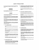
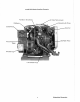
4.5 KW BeG Marine Gasoline Generator Fuel Shut - off So,IAnoirl Air Intake Flame Arrestor with Choke Control Governor L ..........
4.5 KW BeG MARINE GASOLINE GENERATOR SET GENERAL SPECIFICATIONS Engine Type Gasoline, four-cycle, three-cylinder, fresh water-cooled Vertical, in-line overhead valve mechanism (8 bhp at 1800 rpm, maximum). Governor Hoof, flyball type, 5% speed regulation. Combustion Chamber Multi-sphere type. Bore & Stroke 2.44 x 2.38 inches (62.0 x 60.5 mm) Piston Displacement 33.4 cubic inches (.547 liter) Firing Order 1-2-3 Direction of Rotation Clockwise, when viewed from the front.
4.5 KW BCG SYSTEM SPECIFICATIONS INTAKE SYSTEM Carburetor (STD type) Manual with butterfly shaped valve. single barrel with U.S.C.G. approved flame arrester. IGNITION SYSTEM General Battery ignition, 12-volts (negative ground), distributor with points, ignition coil and spark plugs. Distributor Conventional, contact-point type. Spark Plug Thread Size 14 x 1.25 mm pitch (0.55 x 0.05 in.) Spark Plug Type Westerbeke part number 33805 (Always identify the generator model when ordering parts.
4.5 KW BCG SYSTEM SPECIFICATIONS Sea Water Flow, at 1800 rpm (measured before discharging into exhaust elbow) 3.75 - 4.0 U.S. gpm (14.19 - 15.14Ipm) System Capacity (fresh water) 4.2 U.S. qts (3.9 liters) LUBRICATION SYSTEM General Fully - Force fed type by Trochoid pump, crankshaft-driven. Oil Filter Full flow, paper element, spin-on type. Sump Capacity (not including filter) 3.0 qts (2.8 liters) Operating Oil Pressure (engine hot) 50 - 70 psi (3.5 - 4.
4.5 KW BCG SYSTEM SPECIFICATIONS AC GENERATOR General Brushless, four-pole, revolving field. Self exciting. Capacitor saturated field excitation. Pre-lubricated, single-bearing design. Reconnectable 120 volts or 120/240 volts, single-phase. Voltage 120 or 120/240 volts - 60 hertz 220 volts - 50 hertz. Voltage regulation: ± 5% no-load to full-load. Frequency regulation: ± 3 hertz (5%) no-load to full-load. Rating (volts AC) 60 Hertz (1800 rpm) 120 volts 120/240 volts 37.5 amps 37.5/18.
INSTALLATION CHECKS General Since the crafts in which Westerbeke generators are installed vary in design, installation procedures will vary according to your craft's specific design. The intent of this section is not to advise boatyards or installers on procedures alreadywell-developed and well-understood.
Rigging and lilting The generator is fitted with lifting eyes. Rope or chain slings capable of supporting the generator's weight should be attached to the eyes and the generator lifted by means of tackle attached to these slings. The lifting eyes have been designed to carry the full weight of the generator; therefore, auxiliary slings are not required or desired. CAUTION Slings must not be so short as to place significant stress on the generator's lifting eyes.
Generator Mounting - Location The complete generator unit is mounted on lightweight rails by means of four flexible isolator mounts that help preventthe transfer of vibration from the generator to the rails. Each generator mounting rail has several 1/2 inch bolt holes so bolts can be employed to properly secure the generator to its mounting platform. These holes are on 15 inch mounting centers.
Exhaust System ~WARNINGi Carbon monoxide gas is deadly! Carbon monoxide is a dangerous gas that can cause unconsciousness and is potentially lethal. Some of the symptoms or signs of carbon monoxide inhalation or poisoning are listed below.
Exhaust Back-Pressure The exhaust discharge hose !111.lfl1 be of adequate size and minimal run to prevent excessive exhaust back-pressure. Exhaust back-pressure should be checked before a generator is put into service. (Refer to the illustration.) Excessive back-pressure will affectthe engine's performance which affects generator AC power output. -Insulation To measure for back-pressure, use a mercury manometer, a pressure gauge, or a water column.
Dry stack-type exhaust systems (shown to the right) l1lJ.lS1: be attached to the generator engine's exhaust manifold by means of a flexible connector pipe. This system lIlll.&be properly supported and insulated to prevent water from entering into the engine's cylinders. Provisions l1lJ.lS1: be made for discharging the engine's cooling sea water. FLAPPI:II: COV~III ---;P4' iI o- M'" .1 1/01# l: • P _ s. "1: .. 1: .. :ITCH OOWH 1/01 r::XHAUST To ::tHeH - C
Exhaust Elbow Installation The Westerbeke Corporation offers a 45'and 90'exhaust elbow as well as an exhaust riser you can install on your generator. Refer to the instructions below when installing the exhaust elbow purchased for your generator. NOTE: Fabricated exhaust elbows or risers attached to the exhaust manifold shall not exceed S Ibs when unsupported. 1. Coat only one side of the exhaust gasket with '''High Tack" adhesive sealant.
Fuel System The generator lilll3.1 have its own fuel supply line; in other words, it lilll3.1 have its own fuel tank pickup tube and primary filter/water separator. Do no\ tee off another engine's luel supply. Installations where the fuel tank(s) are at or above the generator, with the fuel supply lines 10 the engine's carburetor routed below the level of the fuel tank's top, lilll3.1 have a means of shutting off the fuel to the generator's engine when the engine is not running.
~ ~ ANTI-SIPHON DEVICE OR ELECTRICALLY OPERATED FUEL STOP VALVE --- -;::-~~~~o;,.
Oil Drain Hose An oil sump drain hose is installed on the engine with the discharge end secured by a bracket at the front of the engine. Oil may be drained from this hose by removing the cap and the discharge end of the hose from the support bracket and lowering the hose into a container. The hose cap fitting is 1/4 inch NPT (National Pipe Tap) and can be extended or have a pump added, by the operator, for easier removal of the old oil, if desired.
CAUTION Do not use a scoop or weedless scoop-type through-hull fitting as a means of supplying sea water to the generator. Water pressure against this type fitting, while the vessel is under way, can push sea water past the sea water pump's impeller into the generator's exhaust system, filling it and the engine's cylinders as well. Flush-type, clear, through-hull fittings are recommended and should be located on the hull so as to be below the watertine during all angles of boat operation.
exhaust temperature (an inadequate supply of sea water coolant causes high exhaust temperatures). This switch opens at 260 - 270' F (127 -132' C) and resets at approximately 225' F (107' C). High Water Temperature Shutdown Switch (normally closed) A high water temperature switch is located on the thermostat housing. This switch will open and interrupt the DC voltage to the ignition coil (which turns OFF the engine), should the fresh water coolant's operating temperature reach approximately 205' F (96' C).
Ventilation The ventilation requirements of the generator sets include the following: combustion air is required for the engine cylinders; cooling air is required for the generator end and also for removing the heat produced by the generator's engine during operation; and ventilating air is required to clear the bilges below the generator, as well as the compartment in which the generator is located, of potentially toxic and flammable gasoline vapors.
DESCRIPTION OF ENGINE CONTROL PANEL General The engine-mounted control panel is equipped with an ON switch, a START switch, and a STOP switch. The panel also has two fuses to protect the DC circuit. The three switches serve the following functions: 1. ON Switch· The ON switch provides power to the START circuit. This switch also bypasses the protective oU pressure shutdown switch until the engine's oU pressure reaches 10 - 15 psi. 2.
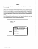
Optional Remote Instrument and Remote Start Panels An optional remote instrument panel is available, which includes starting controls. This panel also includes a water temperature gauge, oil pressure gauge, battery voltmeter, operating hourmeter and start-stop control switches. REMOTE INSTRUMENT PRNEL REMOTE START PANEL The remote instrument panel has with it two sending units to be installed on the engine block. One, a water temperature sender and the other, an oil pressure sender.
PREPARATIONS FOR STARTING This section of the manual provides the operator with preparation, initial starting, break-in, starting (cold or warm), and stopping procedures. Follow the procedures as presented, for the conditions indicated, and your Westerbeke generator set will give you reliable performance and long service life. Take the steps described below in starting your engine for the first time or after a prolonged shutdown or layup.
STARTING PROCEDURE ~WARNINGi Carbon monoxide exhaust gas is deadlyl 1. Ventilate the generator compartment for a minimum of 5 minutes prior to starting the generator. The ventilating blowers remove potentially explosive gasoline fumes from the generator compartment and bilge. 2. Depress the ON switch and hold it depressed for 5 to 15 seconds to make sure the fuel system on the engine is primed to the carburetor. Continuing to depress the ON switch, proceed to step #3. 3. Depress the START switch.
Remote Starling Procedure The remote start panel is the same as the engine-mounted start panel except that it has a green LED light. When starting at a remote location, the green LED lights when the generator is running at approximately 600 rpm, which indicates when the START switch can be released, since the starting of the generator may not be audible. A. When starting the generator set at a remote location, release the START switch when the green LED lights, but continue depressing the ON switch.
STOPPING PROCEDURE 1. Remove the AC electrical load from the generator and allow the generator to run for 3 to 5 minutes to stabilize its operating temperatures. 2. Depress the STOP switch and hold it until the generator is completely stopped. 3. Now release the STOP switch. Break-In Precautions Because the generator set operates at 1800 rpm to produce 60 hertz, or at 1500 rpm to produce 50 hertz, control of the generator's engine break-in is governed by the current drawn from the generator.
Start the generator, following the procedure outlined in the "STARTING PROCEDURE" section, page 28, and allow the engine's operating temperature to reach 130 -150° F (55 - 66° C) before placing the generator under a heavy load. Starting Under Cold Conditions Under extremely cold temperatures, the following conditions can occur. Follow the instructions listed below when operating your generator set in cold weather.
CARBURETOR AND FUEL SYSTEM Gasoline Use unleaded or leaded gasoline with an octane rating of 89 or better. I n cold weather particularly, water vapor is produced by condensation when air is present in the fuel tank. Keep fuel tank(s) full and completely free of dirt and water. The carburetor is a single barrel, down-draft type with a cleanable metal screened air intake filter/spark arrestor. Screened Cleaner .
Optional Fuel Filter/Water Separator A primary fuel filter of the water separating type lI1.LI.iit. be installed between the fuel tank and the engine. This is to remove water and other contaminants from the fuel before they can be carried to the fuel system on the engine where they can cause unwanted engine stoppage and damage to the fuel system equipment on the engine.
The engine mounted fuel pump requires little or no maintenance. Ensure fuel being supplied to this pump is free of water or other types of contaminants that will hinder the pumps operation. Periodically check the fuel connections to and out of the pump and make sure that no leakage is present and that the fittings are tight and secure. Also, check that the DC electrical connection supplying 12 volts DC to the pump is clean, tight and secure.
ELECTRICAL SYSTEM Engine 12-Volt DC Control Circuit The engine that drives the generator end has a 12-volt DC electrical control circuit, as shown on the wiring diagram which follow on pages 38 and 39. Refer to these diagrams when troubleshooting or servicing electrical components on the engine. CAUTION To avoid damage to the battery's charging circuit, never shut off the engine's battery switch while the engine is running.
Testing the Battery Charging Circuit 1. AC Stator Winding: 0.14 Ohm Lift the two AC leads off the bridge rectifier and measure with an ohmmeter the resistance between these two leads which should measure 0.14 ohm. No continuity should exist between these two leads and the ground. 2. Bridge Rectifier Normal AC voltage running to the rectifier (while the engine is operating at 1800 rpm) is measured across the two AC connections on the bridge rectifier. (See the illustration below.
D. With the (-) negative lead still connected to pOint #4, touch point #5. The needle should not deflect. E. Place the (+) positive lead on point #1 and the (-) negative lead on point #3. The ohmmeter again should not register any deflection (no deflection indicated infinite resistance). Reverse these connections and the ohmmeter should again register no deflection. If the rectifier fails any of the previous tests (A - E), replace the rectifier because it is defective.
DC CONTROL CIRCUIT WIRING DIAGRAM #38028 Page 1 of 2 E!J,.
DC CONTROL CIRCUIT WIRING DIAGRAM #38028 Page 2 of 2 SCHEMATIC DIAGRAM 12 VDC BATTERY 1--,------------'---1IIIiIf--I.___ r--- .--- '-~-l : ! \ I CIRCUIT 8REAKER d: I -~ I .Of-----~jll~. STARO' ''".'.''.'.'' __________. ______________.., • ._ 20AI.IP J I BATTERY r-HAR{;[R CHOKE SOl-EI'lOID 0 I CARe SOLENOID PUMP '" I BALLAST + RESISTOR + COIL DISTRIBUTOR 1 ..L OIL PRESSURE f"'" EXHAUST TEt.4P ~ SW"" STOP SWITCH WATER TEMP.
OPTlO/0AL ~'EMOTE START PAiJEL (REAl< VIEW) P. iJ. 33703 ~------- -----------------~ I "110 RED ::;: m I ~IZ YEUvJ/RED 1 2I- STRIPE m ~ c---+l0 r- ::0 ~ G~ ~ m s: ~~ ""~ 'C:JV) " eI "" ::) ~ ~ ...... ~ I 1 1"14 RED/W/PW2 ~ TO T51- Z ~ "12. YEL/W/PED OJ STRIPE " e e T3-1 I Ie "Ib PURPLE 01 T3-Z.
('! o k'EMOTE r·~ ,, " I 00 I CO M I,' '!to ~IZ ::;; (!! « I C YEL/wIRED STRIPER u I~r- ····j z Il'/Z a: TO T81-Z. , I,14RED /'w'/PUR I TOTBI-4 ....... __ : 1f14PURPL£ w QUICK. COJ.)tJEC T..... TERMIIJAL w b::;; TERMiNAL 0:: jl4HLACK I TO TSH II BT440 1 .-"'I I 'lbTAN E rJ-' I :z I I I ...J Ii: o ~:~t=J=:::: I, TOTBI-5 • V·,,, ~ f4 5 ;;J BLACK •. I j STRIPE ... I '14 Y~E5;L!c/~"'/~R~£~D~_ _ _ _ _ _ _ _ _ _ _ _ _ _ _ _ _ .
COOLING SYSTEM Description Westerbeke marine gasoline engines are designed and equipped for fresh water cooling. Heat produced in the engine by combustion and friction is transferred to the fresh water which circulates throughout the engine. This circulating fresh water cools the engine block and its internal moving parts. The heat is transferred externally from the fresh water to sea water by means of a heat exchanger, similar in function to an automotive radiator.
ANTIFREEZE CONCENTRATION DATA Antifreeze Concentration Freezing Temperature % 13 23 30 'F 23 (-5) 14 (-10) 5 (-15) (' C) 35 45 -4 -22 (-20) (-30) 50 60 -40 -58 (-40) (-58) NOTE: An antifreeze concentration should be selected on the basis of a temperature which Is about 10' F (5' C) lower than the actual atmospheric temperature expected. B. Filling the Fresh Water System A coolant recovery tank kit is supplied with each Westerbeke gasoline generator.
FUNCTION OF MANIFOLD PRESSURE CAP From Coolant Tank COOLANT RETRACTION to Coolant Tank Coolant from the engine, when heated during the engine's operation, will expand, lift the spring-loaded manifold pressure cap and enter the recovery tank via the hose connecting the recovery tank to the manifold.
Sea Water Circuit The sea water flow is created by a belt-driven, positive displacement, neoprene impeller pump. The pump draws sea water directly from the ocean through the sea cock and sea water strainer and passes the water to the heat exchanger's sea water inlet. The sea water passes through the heat exchanger's tubes, from around which the fresh water coolant mixture circulates.
Governor/Fresh Water/Sea Water Pump Bell Tension Never attempt to adjust the drive belt's tension while the engine is in operation. CAUTION Excessive governor and water pump drive belt tension can cause rapid wear of the belt and reduce the service life of the fresh water pump and governor shaft bearings. Excessive slack or the presence of oil on the belt can cause belt slipping, resulting in high operating temperatures, as well as poor regulation during generator load changes.
Illustrated below is a typical Westerbeke engine's cooling system. Both fresh water and sea water flow through their independent cooling circuits. Please refer to the Parts List for individual part numbers and descriptions for your generator's cooling system.
LUBRICATION SYSTEM Engine Oil For the engine's lubrication, use a lubricating oil designated for gasoline service. Use a good grade of oil having an API specification of SE, SF or SG. Do not use oils designated OS. Engine Oil Viscosity (SAE Number) Use oil having a viscosity best suited to the atmospheric temperature. Refer to the oil viscosity chart below.
Engine Oil Change (to include filler) 1. Draining the Oil Sump Discharge the old oil through the sump drain hose (attached at the front of the engine) while the engine is still warm. Drain the old oil completely, replace the hose in its bracket, and replace the end cap securely. ~11\11111'lli\I!!llilillli':i":::i!;:' !III !1 \' II': 11:1; ;,:;:,' 'I' , i'" !' I , ;; Always observe the old oil as it is removed. A yellow/gray emulsion indicates the presence of water in the oil.
3. Filling the Oil Sump Add fresh oil through the oil filler cap on the valve cover. After refilling the oil, run the engine for a few moments while checking the engine's oil pressure. Make sure there is no leakage around the new oil filter or from the oil drain system, and stop the engine. Then check the quantity of oil with the dipstick. Fill to, but not over, the high mark on the dipstick, should the engine require additional oil.
Be GENERATOR The BC generator is a brushless, self-excited generator which requires only the driving force of the engine to produce an AC output. The stator houses two sets of windings: the main stator windings and the exciter windings. When the generator is started, residual magnetism in the four rotating poles induces a current in the stator exciter windings.
No-Load Voltage Adjustment: 4.5 KW BCG 1. Remove the louvered metal plate covering the terminal connections and the capacitor (see page 53). 2. Start the generator and allow it to run for approximately five minutes so the engine can warm up. Make sure the generator is operating without any equipment drawing AC current from the generator (that is, shut OFF all electrical appliances).
THE _7 PLUG IS SHOWN CONNECTED TO THE CAPACITOR ONLY FOR DEMON- STRATION PURPOSES. BCG 4.5 kW GEHERATOR AC load Connection Terlllinal Block Generator End Cover Plate No-load Voltage 50 Hertz Plug DO NOI ANV OF TH~G~ TO TOU~H THE G~NERATOR·S HOUSING. WINDINGS WILL DURN IF THESE PLUGS TOUCH THE HOUSING OR OTHER WIRES. CAllI ION, ALLOW PLUGS A. Check the resistance of the exciter windings B. Check the capacitor. 4.5 't
Load Connections The generator's data plate gives the voltage, current and frequency rating of the generator. An AC wiring decal is affixed to the inside of the louvered cover on the generator end. A diagram of the various AC voltage connections is provided on the decal. The generator is a single-phase, reconnectable 120 volts AC two-wire or 120/240 volts AC three-wire, at 60 hertz; or 110 volts AC two-wire, 110/220 volts AC three-wire, or 220 volts AC two-wire, at 50 hertz.
Shore Power Connections If the installer connects shore power to the vessel's AC circuit, this must be done by means of the SHORE POWER/OFF/SHIPS GEN., center position-off transfer switch shown below. Use of this switch prevents simultaneous connection of shore power to generator output. CAUTION Damage to the generator can result if utility shore power and generator output are connected at the same time.
NOTES Westerbeke Generators 56
GENERAL INFORMATION AND CARE OF THE GENERATOR Use 01 Electric Molars The power required to start an electric motor is considerably more than is required to keep it running after it is started. Some motors require much more current to start than others. Split-phase (AC) motors require more current to start, under similar circumstances, than other types.
4-Pole Speed (rpm) Frequency (Hertz) Generator 120V (110) Plants Voltage 240V (220) Plants None 1830 (1530) 62 (52) 122 (112) 240 (224) Half 1800 (1500) 60 (50) 120 (110) 240 (220) 1755 (1455) 59 (49) 110 (100) 220 (200) Load Applied Full The output voltage should be checked periodically to ensure proper operation of the generating plant and the appliances it supplies.
ENGINE TROUBLESHOOTING Introduction The tables which follow indicate troubleshooting procedures based upon certain problem indicators, the probable causes of the problems, and the recommendations to overcome these problems. Note that the engine's control system (electrical system) is protected by a 20-Ampere manual reset circuit breaker located next to the starter motor and the (-) ground terminal.
Possible Cause Tro!Jble 6. Bad starter solenoid. 7. Faulty START switch. 1. Faulty automatic shutdown switch (oil, water, or eXhaust). Engine starts, runs and then shuts down. 2. Faulty overspeed switch (reset and start; bypass switch to test). 3. Faulty fuel pump. 4. Faulty STOP switch. 5. Engine circutt breaker is tripping. 6. Dirty fuel filters. 7. Low oil level in sump. 8. Mechanical check valve at the fuel supply fuel pump is unable to draw fuel through this valve. 1. Ignition timing is wrong.
Trouble possible Cause 5. Faulty hose. 6. Thermostat is stuck closed. 7. Heat exchanger is clogged. 8. Faulty gauge (check with a thermometer). Engine hunts. 1. Throttle linkage is binding. 2. Dirty fuel filters. 3. Defective fuel pump. 4. Governor is out of adjustment. 5. Valves are out of adjustment. 6. Generator is overloaded. 7. Cracked distributor. 8. Faulty high-tension leads. Engine misfires. 1. Ignition timing is wrong. 2. Spark plugs are worn. 3. Valve clearances are incorrect. 4.
Possible Cause TrolJble 1. Low oil level. Low oil pressure. 2. Faulty gauge. 3. Wrong SAE type oil in the engine. 4. Wrong type oil filter. 5. Relief valve is stuck. 6. Faulty oil pump. 1. DC connections to the controller are loose or faulty. No DC charge to the starting battery. 2. Faulty controller circuit component. 1. Dirty air intake. Black exhaust smoke is discharged from the engine. 2. Choke is stuck closed. 3. Carburetor is flooding. 1. Valves are worn or adjusted incorrectly.
MAINTENANCE AND ADJUSTMENTS Introduction This section contains a scheduled preventive maintenance program and several adjustment procedures the owner/operator can perform without the benefit of sophisticated and expensive tools and instruments. Preventive Maintenance (Engine) Perform the preventive maintenance in accordance with the schedules listed in the following paragraphs.
*3. Retorque the cylinder head bolts. *4. Adjust valve clearances. 5. Adjust Governor/Fresh Water pump and Sea Water pump drive belt tension, if required. 6. Adjust the engine's no-load speed, if required (hertz). Please note that this adjustment is not a warrantable adjustment during or after the unit's break-in. *7. Check ignition point gap and engine timing. (Check condition of distributor cap rotor.) Servicing After Every 100 Hours of Operation 1. Change the engine's lubrication oil and oil filter. 2.
Servicing After Every 1000 Hours 01 Operation Remove, clean, and pressure lest the primary heat exchanger. (A local automotive radiator shop should be able to clean and test the heat exchanger.) NOTE: Operating in silty and/or tropical waters may require that a heat exchanger cleaning be performed more often than every 1000 hours.
Ignition Timing 1. Attach a timing light to the #1 spark plug and mark the front timing pointer to indicate 11". Locate the timing mark on the crankshaft pulley and mark IT with white chalk or crayon. 2. Start the engine and warm it up to its normal operating temperature. Make sure the generator is ope rat ing without a load on it. 3. Using the timing light, align the timing mark in the front crankshaft pulley so it is just slightly before the 1O"mark of the timing pointer.
Governor Adjustments Operate the generator set to bring the unn up to its operating temperature before attempting an adjustment. NOTE: If the governor is severely out of adjustment, manually adjust the linkage without any load on the generator to obtain a safe output voltage before proceeding with the adjustment. Three adjusting points are on the governor. (Refer to the illustration below.) 4.5 f
2. Governor oil capacity: 4.5 'r
Torquing Cylinder Head Bolls Tighten the cylinder head bolts according to the sequence shown in the illustration below. Make sure the engine is cold when this is done. Loosen one head bold one-half turn and then tighten it to the specified torque. Then proceed to the next head bolt in the sequence numbering shown. BCG 4.S KW TIGHTENING SEQUENCE Torque Specifications: 4.5 IWV BeG 36.2 - 43.4 Ib-ft (5.0 - 6.
Valve Clearance Adjustment: 4.5 KW BeG ADJUST EXHAUST VALVES TO 0.012 INCHES NOTE: Retorque the cylinder head bolts before adjusting the engine's valves. (0.30 MM) ADJUST INTAKE VALVES TO 0.010 INCHES (0.25 MM) 1. Remove the rocker cover and the gasket. 2. Carry out the check and adjustment of valve clearances, with the piston of the No.1 cylinder positioned at the top of ITS compression stroke and the exhaust and intake valves completely closed.
LAY-UP AND RECOMMISSIONING General Many owners rely on their boatyards to prepare their craft, including engines and generators, for lay-up during the off-season or for long periods of inactivity. Others prefer to accomplish lay-up preparation themselves. The procedures which follow will allow you to perform your own lay-up and recommissioning, or to use as a check list IT others do the procedures.
Sea Water Circuil Close the through-hull sea cock. Remove the sea water intake hose from the sea cock. Place the end of this hose into a 5-gallon bucket of clean fresh water. Before starting the engine, check the zinc anode found in the primary heat exchanger on the engine and clean or replace it as required. Clean the sea strainer, if one is installed, in the inside of the hull. Start the engine and allow the sea water pump to draw fresh water through the system.
Batteries If batteries are to be left on board during the lay-up period, make sure they are fully charged, and will remain that way, to prevent them from freezing. If there exists any doubt that the batteries will remain fully charged or that they will be subjected to severe environmental conditions, remove the batteries and store them in a warmer, more compatible environment.
SPARE PARTS LIST Since a possibility exists in which the engine may need to be serviced at sea or while in a port other than your home port, certain spare parts should be kept on board to help minimize delays in your voyage. Please refer to your engine's Parts List for part numbers when ordering spare parts. Listed below are those spare parts that should be carried on board at all times. 1. A Sea Water Pump Impeller Kit 2. A Filter Screen for the Inlet to the Carburetor 3.
TABLE OF STANDARD HARDWARE TIGHTENING TORQUES Unless stated otherwise for a specific assembly, use the following torque values when tightening standard hardware. Pitch Ib-ft kg-m Grnd!llI 6mm bolt head/nut Bmm bolt head/nut 10mm bolt head/nut 10mm bolt head/nut 12mm bolt head/nut 12mm bolt head/nut 12mm bolt head/nut 13mm bolt head/nut 14mm bolt head/nut 14mm bolt head/nut 16mm bolt head/nut 16mm bolt head/nut 1.25 1.25 1.5 1.25 (ISO) 1.5 1.75 1.5 1.5 2 1.5 2 2.9 - 5.1 7.2 - 11.6 13.7-22.4 13.0- 21.7 25.
TABLE OF TIGHTENING TORQUES Cylinder Head Bolts' l.b:!t kQ:ill 36.2 - 43.4 5.0 - 6.0 (·See the Torquing Cylinder Head Bolts section on page 68.) Crankshaft pulley to crankshaft 36.2 - 43.4 5.0 - 6.0 Rocker cover to cylinder block 2.9 - 5.1 0.4 - 0.7 10.8 - 15.2 1.5 - 2.1 Timing belt cover #1 3.2 - 4.8 0.44 - 0.66 Timing belt cover #2 5.2 - 7.8 0.72 - 1.08 Timing belt tensioner 23.1 - 34.7 3.2 - 4.8 Valve adjusting screws 9.4 -13.0 1.3 -1.8 Oil pan drain plug and oil pan 25.3 - 32.
INDEX A Automatic Shutdown ................................................................................................................................... 22 B Back-Pressure, Exhaust .............................................................................................................................. 16 Batteries .......................................................................................................................................................
Electrical Connections, DC .........................................................................................................................22 ELECTRI CAL SYSTEM ................................................................................................................................35 Electrical System .........................................................................................................................................22 Engine 12 - Volt DC Control Circuit .................
L LAY-UP AND RECOMMISSIONING ........................................................................................................... 71 Load Connections ....................................................................................................................................... 54 LUBRICATION SYSTEM ............................................................................................................................. 48 Lubrication System ................................................
s Sea Water Circuit ...................................." .......................................................................................... 45 & 72 Sea Water Intake System ............................................................................................................................21 Sea Water Pump ..........................................................................................................................................45 Shore Power Connections ........................
W WARNING CARBON MONOXIDE GAS IS DEADLy!.. ............................................................................... 15 & 28 DO NOT ATTEMPT A NO-LOAD ADJUSTMENT WITH ENGINE ON ................•.•••••.....••••••............. 52 DO NOT SMOKE NEAR BATTERIES ....................•••••.••....................•••••.......••••••.......•.................... 23 EXCESSIVE DRIVE BELT SLACK OR TENSiON ...•••.............•••••••....•..•••.......••................................ 46 GASOLINE LEAKAGE .••••............
NOTES Westerbeke Generators 82