
Operator`s manual

CAUTION
Do
not
use a scoop
or
weedless scoop-type through-hull fitting as a means
of
supplying sea
water
to
the generator. Water pressure against this type fitting, while the vessel
is
under way,
can push sea water past the sea water pump's impeller into the generator's exhaust system,
filling
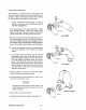
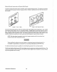
it and the engine's cylinders as well. Flush-type, clear, through-hull fittings are recom-
mended and should be located on the
hull so as
to
be below the watertine during all angles
of boat operation.
The use of common-type street elbows
is
not recommended for plumbing the sea water circuit. These
generally have very restrictive inside diameters. Machined fittings with true inside diameters are preferred.
Electrical System
The
electrical system should be checked
to
make sure all wires and harnesses are property tied down with
clamps
or
plastic ties and that all wiring harnesses are supported at intervals close enough to prevent chaf-
ing from vibration. Check to make sure
all engine harness connections are tight and that they are made to
the appropriate terminals.
Also, ensure that these terminals are not the recipients of bilge water
or
water
from
leaky hatch covers or corrosion will result.
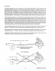
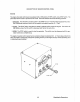
DC
Electrical
Connections
A tagged common ground stud for the negative
(-)
DC
terminal connection
is
found at the bell housing of the
generator, next to the
starter,
in
the form
of
a threaded grounding stud. The DC battery ground should be
connected at this stud.
Connect the battery's positive
(+)
connection to the starter solenoid tagged for this connection.
CAUTION
To
avoid an overcharging condition and a possible equipment failure,
do
not
disconnect the
DC battery source while the engine
is
running.
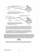
Grounding
The generator set ll!.f.mt be grounded
to
comply with United States Coast Guard regulation 33 CFR-183 which
specifies that a common conductor be connected between the generator set and the
vessel's main propul-
sion engine's grounded starter motor circuit. This conductor (the common ground) prevents accidental pas-
sage of cranking current through
fuel systems and smaller electrical conductors common
to
the engines.
This conductor
ll!.f.mt be the same size
as
the largest battery cable.
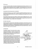
Automatic
Shutdown
High Exhaust Temperature Shutdown Switch (normally closed)
An
exhaust temperature switch
is
located on the exhaust elbow. This switch will open and interrupt the
DC
voltage
to
the ignition coil (which turns OFF the engine), should the switch's sensor indicate an excessive
Westerbeke Generators
22