
Operator`s manual


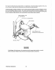

Testing
the
Battery Charging
Circuit
1.
AC Stator
Winding:
0.14 Ohm
Lift the two
AC
leads off the bridge rectifier and measure with
an
ohmmeter the resistance between these
two leads which should measure
0.14 ohm. No continuity should exist between these two leads and the
ground.
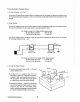
2.
Bridge Rectifier
Normal
AC
voltage running to the rectifier (while the engine
is
operating at 1800 rpm) is measured across
the two
AC
connections on the bridge rectifier.
(See
the illustration below.)
AC
voltage running
to
the bridge rectifier (approximate):
No-load off the generator 16.0vollS
AC
Full-load off the generator 17.5 volts
AC
Normal
DC
voltage running out of the rectifier
(in
volts
DC)
is measured across the two DC connections
of the bridge rectifier; that
is,
+ and - .
AC
+
AC
-I>I-
LC.
DC
CHARG
BRIDGE
RECTIFIER
INTEGRAL
CONTROllER
DC voltage running from the bridge rectifier (approximate):
No-load off the generator 17.0 volts DC
FUll-load off the generator 18.5 volts
DC
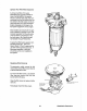
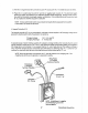
3.
Testing the Bridge Rectifier
A.
Set your ohmmeter's scale on
RXI
(+
DC)
and
set the needle
to
zero.
B.Connect
the
(+)
positive
lead
from
the
ohmmeter
to
point
#4.
Taking the ohmmeter's
negative
(-)
lead, momentarily touch points
#i,
#2,
#3, and
#5.
The ohmmeter should register
no deflection for any of the points touched.
C.
Remove the positive ( + ) lead from point
#4
and
connectthe negative
(-)
lead
to
point
#4.
Touch
points #1,
#2,
and
#3.
The needle should
deflect, indicating a passage of current through
the diodes located internally at these points.
Westerbeke Generators
Point
.,2
36
Point
tfS
(Rectifier Mounting Hole)
_Point
113