
Operator`s manual


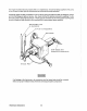

D.
With the
(-)
negative lead still connected
to
pOint #4, touch point
#5.
The needle should not deflect.
E.
Place the
(+)
positive lead on point #1 and the
(-)
negative lead on point
#3.
The ohmmeter again
should not register any deflection (no deflection indicated infinite resistance). Reverse these connec-
tions and the ohmmeter should again register
no
deflection. If the rectifier fails any of the previous tests
(A
-
E),
replace the rectifier because it
is
defective.
NOTE: Various style/model meters may produce test results directly opposite from tests
B-E.
In such tests, the results are as above.
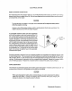
4.
Integral Controller (I.C.)
The integral controller (I.C.)
is
an encapsulated, solid-state unit that supplies a DC charging voltage to the
generator's starting battery while the generator
is
operating.
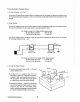
Charging
Voltage: 13.0 -14.0 volts DC
Charging Amperage:
0 -
10
amps DC
A separate group
of
stator windings supplies
AC
voltage to a bridge rectifier which converts the
AC
current
into
DC
current to supply the
I.C.
unit. The
I.C.
unit senses the needs of the starting battery and supplies a
DC charge when one
is
needed. If you suspect that the
I.C.
unit
is
faulty (that
is,
if the battery's charge
is
low), check the charging circuit's components and performance by following steps #1 -
3.
Check
all
con-
nections for
cleanliness and tightness including the ground before replacing the
I.C.
unit.
NOTE: When the generator
is
first started, the
I.C.
unit will produce a low charging
rate.
This
charging rate
will rise as the generator
is
operated for awhile.
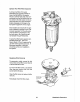
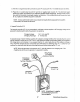
Whhe/Green
(-) Negative
Terminal
of
Rectifier
White/Red
D.C. Charge
37
WMeIYeliow
(
+)
Positive
Terminal
of
Rectifier
White/Black
Ground
~
NOTE: White/Green
(-)
negative
and White/Black ground are
Interchangeable.
Westerbeke Generators