
Operator`s manual


Load
Connections
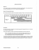
The generator's data plate gives the voltage, current and frequency rating
of
the generator.
An
AC wiring
decal
is
affixed
to
the inside of the louvered cover on the generator end. A diagram of the various AC volt-
age connections
is
provided on the decal.
The generator
is
a single-phase, reconnectable 120 volts AC two-wire
or
120/240 volts AC three-wire, at 60
hertz; or 110 volts AC two-wire, 110/220 volts AC three-wire, or 220 volts AC two-wire, at 50 hertz. Refer to
the
"SYSTEM SPECIFICATIONS" seclion
of
this manual for the 4.5
I<W
BCG generator rating, page
11.
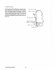
NOTE: The frame ground wire
~
be moved when changing from 110 volts, 50 hertz to /220
volts, 50 hertz.
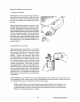
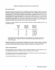
A circuit breaker should be installed between the generator and the
AC load. This circuit breaker should be
rated at
120% of the generator's AC output and be able to react quickly to overloads, subject to motor start-
ing considerations.
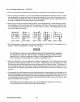
N
L,
N
L,
4 3
483
3e
4e::::a3
5-
e2
6
2e6
582e
68
5e286
L,
110V
50Hz
120V
60Hz
220V
50Hz
60Hz
220V
50Hz
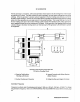
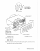
For making connections
to
the AC terminal block, use terminal ends for
#10
studs which will accept mulli-
strand wire sized for the number of conductors in the bundle, the rating
of
the conductor's insulation, and
amperage that will be drawn through the conductor(s). (Refer
to
the generator's data plate for the gener-
ator's amperage and voltage ratings.)
NOTE: When changing hertz produced by the generator, an engine speed adjustment at the
governor
~
be made. The
AC
output connections on the above illustrated terminal blocks
~
be selected for the voltage and hertz
to
be produced. A plug at the capacitor
~
be
changed for
50 (#5)
or
60 (#6) hertz use. Early models with 3 wire connections
tothe
integral
controller require a
50 (#5) or 60 (#6) hertz connection change at the bridge rectifier in the
DC
charging circuit. Refer
to
the "Generator's Internal Wiring Schematic" on page
51.
Westerbeke Generators 54