
Operator`s manual
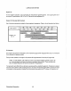


Shore Power
Connections
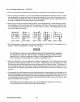
If the installer connects shore power to the vessel's AC circuit, this must be
done
by
means of the SHORE
POWER/OFF/SHIPS
GEN., center position-off transfer switch shown below. Use of this switch prevents
simultaneous connection of shore power
to
generator output.
CAUTION
Damage
to
the generator can result if utility shore power and generator output are connected
at the same time. This type of generator damage is
not
covered under the warranty; it
is
the
installer's responsibility
to
make sure all
AC
connections are correct.
Generator NOIE:
DIAGRAM
SHOWS
CO~MECTIONS
FOR
1110-
~
WHE.
120-VOLT SYSTEM.
fOR
THHf-WIRE
t
T SYSHM
USE
OOTi£D
liNES
FBR
fHE
I OTHH
HOT
LEGS.
I
"------,
I
/'--,
L
_____
,~
~~,_
r-----\~
~/
I '
I
I
I
I
---,
I
I
I
I
I
I
I
SHIP-IO-SHORE
SWITCH
'--+-,
-1---":'/$--'\
~~:]Sh'P'
i
~~-_//
"'"
l
~~
t-""G'~"""-'
~---III"
(3
POL
El
PH
32888
(4\1 MoIPS/POL[)
PH
320ftS
t60
AMPS/POLEl
PH
329111
112S
AMPS/POlEl
PH
32133
OR"
AMPS/POlEl
l 52
51
N
Gener310r
r N
Gl'~
-
Shore
POW!!!
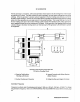
NOTE:
DIAGRAM
SHOWS
CONNECTIONS
FOR
A
TWO-
WIRE,
I20-VOLT
SYSTEM
FROM
THE
GENERATOR,
WITH
THREE-WIRE.
128-VOlT
'-
____
-'B"'O"A"'T-;S
YS
IE
H.
Ship-to-Shore
Sw~ch
(3
pole)
PN
;J;'HHHl
(41'1
"'..,PF;/POt
F)
P,,"
:l~"~>;>
{BI1l
AI-IP6/POLEj
PM
3201,9
(1:;0';
",MPH/POI
F)
PH
32J.33
(299
AMPS/PO!..!::)
Shore Power Switch Connection Diagrams
55
Westerbeke Generators