OPERATOR'S MANUAL WESTERBEKE BCG 4.0KW and BCG 6.5KW MARINE GASOLINE GENERATOR SETS Publication # 35729 Edition Two March 1988 ~ WESI'ERBEKE WESTERBEKE CORPORATION AVDNINDUSTRIAL PARK, AVON, MA 02322.
Gasoline with an ETHANOL content higher than 10% (E10) is not allowed and may void warranty.
------------------------------ -----"'''--~"-------------~, SAFETY PRECAUTIONS The following symbols appear in this manual to call attention to and emphasize conditions potentially dangerous to the operator. • Use Extreme Care When Handling Engine Fuel (A constant danger of explosion or fire exists) Do not fill fuel tank(s) while the engine is running, ~WARNINGII Do not smoke or use an open flame near the engine or the fuel tank.
IMPORTANT PRODUCT SOFTWARE DISCLAIMER Product software of all kinds, such as brochures, drawings, technical data, operator's and workshop manuals, parts lists and parts price lists, and other information, instructions and specifications provided from sources other than Westerbeke, is not within Westerbeke's control and, accordingly, is provided to Westerbeke customers only as a courtesy and service.
FOREWORD Thank you for selecting a Westerbeke marine product for your use. We at Westerbeke are pleased to have you as a customer. Read this manual carefully and observe all safety precautions included throughout.
TABLE OF CONTENTS Section ......................................................................... Page GENERAL ........................................................................... 5 BCG 4.0KW GENERAL SPECIFICATIONS ..................... 10 BCG 4.0KW SYSTEM SPECIFICATIONS ........................ 11 BCG 6.5KW GENERAL SPECIFICATIONS ..................... 14 BCG 6.5KW SYSTEM SPECIFICATIONS ........................ 15 INSTALLATION CHECKS ................................................
TABLE OF CONTENTS (CONTINUED) LAY-UP & RECOMMISSIONING ......................................80 SPARE PARTS LIST ..........................................................83 TABLE OF STANDARD HARDWARE TIGHTENING TORQUES ..................................................84 TABLE OF TIGHTENING TORQUES ...............................85 INDEX ................................................................................
GENERAL Introduction This manual contains the equipment operating procedures as well as additional information needed to help the operator keep the marine equipment in proper working order. Study and follow the instructions carefully. A planned maintenance program is included in this manual; adhering to the program will result in better equipment performance and longer equipment life.
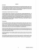
BeG 4.0KW Marine Gasoline Generator Lube Oil Fill Fresh Water Coolant Fill Exhaust Mani Lube Oil Dipstic 0 90 Exhaust Elbow 20 Amp DC Circu Breaker Zinc Anode DC Battery Ground Connection Heat Ex.
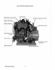
BCG 4.()KW Marine Gasoline Generator Water Tempe ratu re Switch Intake Flame Arrestor rburetor with Choke Fresh Water Air Bleed r.
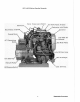
BeG S.
BeG 6.
BCG 4.0KW MARINE GASOLINE GENERATOR SET GENERAL SPECIFICATIONS Engine Type Gasoline, four-cycle, two-cylinder, fresh water-cooled Vertical, in-line overhead valve mechanism (8 hp at 1800 rpm, maximum). Governor Hoof, flyball type, 5% speed regulation Combustion Chamber Multi-sphere type Bore & Stroke 2.82 x 2.68 inches (71.6 x 68 mm) Piston Displacement 33.4 cubic inches (1.
BCG 4.0KW SYSTEM SPECIFICATIONS INTAKE SYSTEM Carburetor (STD type) Down draft type, single barrel with U.S.C.G. approved flame arrester. IGNITION SYSTEM General Battery ignition, 12-Volts, negative ground, distributor with points, ignition coil and spark plugs. Distributor Conventional, contact-point type Spark Plug Thread Size 14 mm x 1.25 pitch Spark Plug Type Westerbeke part number 035666 (Always identify the generator model when ordering parts. See page 5.
BeG II.OKW SYSTEM SPECIFICATIONS Sea Water Flow, at 1800 rpm (measured before discharging into exhaust elbow) 3.75 - 11.0 U.S. gpm (14.19 - 15.14Ipm) System Capacity (fresh water) 3.3 U.S. qts (3.2 liters) LUBRICATION SYSTEM General Pressure type by Trochoid pump, chain-driven through balance shafts. Oil Filter Full flow, paper element, spin-on type Sump Capacity (not including filter) 3,0 qts (2.9 liters) Operating Oil Pressure (engine hot) 50 - 70 psi (3.5 - 4.
BeG 4.0KW SYSTEM SPECIFICATIONS AC GENERATOR General Brushless, four-pole, revolving field. Self exciting. Capacitor saturated field excitation. Pre-lubricated, single-bearing design. Reconnectable 120 Volls or 120[240 Volts, single-phase Voltage 120 or 120[240 Volts - 60 Hertz 220 Volts - 50 Hertz. Voltage regulation: ±5% no load to full load. Frequency regulation: ± 3 Hertz (5%) no-load to fUll-load.
BCG S.!iKW MARINE GASOLINE GENERATOR SET GENERAL SPECIFICATIONS Engine Type Gasoline, four-cycle, three-cylinder, fresh water-cooled Vertical, in-line overhead valve mechanism (14 hp at 1800 rpm, maximum). Governor Hoof, flyball type, 5% speed regulation Combustion Chamber Multi-sphere type Bore & Stroke 2.99 x 2.87 inches (76 x 73 mm) Piston Displacement 60.6 cubic inches (0.
BCG 6.5KW SYSTEM SPECIFICATIONS INTAKE SYSTEM Carburetor (STD type) Down draft type, single barrel wtth U.S.C.G. approved flame arrester. IGNITION SYSTEM General Battery ignition, 12-Volts, negative ground, distributor with points, ignition coil and spark plugs. Distributor Conventional, contact-point type Spark Plug Thread Size 14 mm x 1.25 pitch Spark Plug Type Westerbeke part number 033805 (Always identify the generator model when ordering parts. See page 5.
BCG 6.SKW SYSTEM SPECIFICATIONS Sea Water Flow, at 1800 rpm (measured before discharging into exhaust elbow) 3.75 - 4.0 U.S. gpm (14.19 - 15.14Ipm) System Capacity (fresh water) 5.2 U.S. qts (4.9Itters) LUBRICATION SYSTEM General Pressure type by Trochoid pump, chain-driven through a balance shaft. Oil Filter Full flow, paper element, spin-on type Sump Capacity (not including filter) 3.0 qts (2.9 liters) Operating Oil Pressure (engine hot) 50 - 70 psi (3.5 - 4.
BCG S.5KW SYSTEM SPECIFICATIONS AC GENERATOR General Brushless, four-pole, revolving field. Self exciting. Capacitor saturated field excitation. Pre-lubricated, single-bearing design. Reconnectable 120 Volts or 120/240 Volts, single-phase Voltage 120 or 120/240 Volts - 60 Hertz 220 Volts - 50 Hertz. Voltage regulation: ±5% no load to full load. Frequency regulation: ± 3 Hertz (5%) no-load to full-load.
INSTALLATION CHECKS General Since the crafts in which Westerbeke generators are installed vary in design, installation procedures will vary according to your craft's specific design. The intent of this section is not to advise boatyards or installers on procedures already well-developed and well-understood.
Rigging and Lifting The generator is fitted with lifting eyes. Rope or chain slings capable of supporting the generator's weight should be attached to the eyes and the generator lifted by means of tackle attached to these slings. The lifting eyes have been designed to carry the full weight of the generator; therefore, auxiliary slings are not required or desired. CAUTION Slings must not be so short as to place significant stress on the generator's lifting eyes.
Generator Mounting - Location The complete generator unit is mounted on lightweight rails by means of four flexible isolator mounts that help preventthe transfer of vibration from the generator to the rails. Each generator mounting rail has several 1/2-inch bolt holes so bolts can be employed to properly secure the generator to ks mounting platform. These holes are on 15 inch mounting centers.
Exhaust System IIWARNINGI CARBON MONOXIDE EXHAUST GAS IS DEADLY. Carbon monoxide is a dangerous gas that can cause unconsciousness and is potentially lethal. Some of the symptoms or signs of carbon monoxide inhalation or poisoning are listed below.
Exhaust Back-Pressure The exhaust discharge hose must be of adequate size and minimal run to prevent excessive exhaust back-pressure. Exhaust back-pressure should be checked before a generator is put into service. (Refer to the illustration.) Excessive back-pressure will affect the engine's performance and the generator's power output. To measure for back-pressure, use a mercury manometer, a pressure gauge, or a water column. A boatyard or marine mechanic should have a manometer or a pressure gauge.
Dry stack-type exhaust systems (shown to the right) must be attached to the generator engine's exhaust manifold by means of a flexible connector pipe. This system must be properly supported and insulated to prevent water from entering into the engine's cylinders. Provisions must be made for discharging the engine's cooling sea water. FLAf'PE~ ~lf coVEN .I !' I ---1 ~=====14r.~,L 7'f"".M. MUI"FLI::R XHSUL ,I I: .:! :' TJ:DN '1 ' ~ .1/2" X.F.5. P][I"E PXTI: ..
Exhaust Elbow Installation The Westerbeke Corporation offers a 45°and 900 exhaust elbow as well as an exhaust riser you can install on your generator. Refer to the instructions below when installing the exhaust elbow purchased for your generator. 1. Coat only one side of the exhaust gasket with ·"High Tack" adhesive sealant. Place this coated surface against the exhaust manifold's exhaust port flange (the gasket should stick to the flange without falling off). 2. Place the clamp over the elbow's flange.
Fuel System The generator must have its own fuel supply line; in other words, it must have fis own pickup tubes and primary filter/water separator. DO NOT tee off another engine's fuel supply. Installations where the fuel tank(s) are at or above the generator, with the fuel supply lines to the engine's carburetor routed below the level of the fuel tank's top, must have a means of shutting off the fuel to the generator's engine when the engine is not running.
.~ ~ --- AMTI-SIPHON DEVICE OR ELECTRICALLY OPERATED FUEL STOP VALVE --~~~)"""";-:::";-:::::~/~-7::~~~F~U~E~L~TA~N~K~T:o:p~L~E~V:E~L~:/""~~i~~~~""","'-I FUEL LINE BELOW FUEL TANK lOP LEVEL ANTI-SIPHON DEVICE OR ELECTRICALLY OPERATED FUEL STOP VALVE AT fUEL TANK WITHDRAWAL FITTING I fU EL TANK lOP LEVEL ~ ANTI-SIPHON DEVICE OR ELECTRICALLY OPERATED FUEL STOP VALVE FUEL LIKE ABOVE FUEL TANK T OP lE~V~EL~;_~=-~~.::::.
Oil Drain Hose An oil sump drain hose is installed on the engine with the discharge end secured by a bracket at the front 01 the engine. Oil may be drained from this hose by removing the cap and the discharge end of the hose from the support bracket and lowering the hose into a container. The hose cap fitting is 1/4 inch NPT (National Pipe Tap) and can be extended, or have a pump added, for easier removal of the old oil, if desired.
CAUTION DO NOT use a scoop-type through-hull fitting as a means of supplying sea water to the generator. Water pressure against this type fitting, while the vessel is under way, can push sea water past the sea water pump's impeller into the generator's exhaust system, filling it and the engine as well. Flush-type, clear, through-hull fittings are recommended and should be located on the hull so as to be below the watertine during all angles of boat operation.
High Water Temperature Shutdown Switch (normally closed) A high water temperature switch is located on the thermostat housing. This switch will open and interrupt the DC voltage to the ignition coil (which turns OFF the engine), should the fresh water coolant's operating temperature reach approximately 205' F (96' C). This switch resets at 195' F (107' C). Low Oil Pressure Shutdown Switch (normally open) A low oil pressure shutdown switch is located off the engine's oil gallery.
Ventilation The ventilation requirements of the generator sets include the following: combustion air is required for the engine cylinders; cooling air is required for the generator end and also lor removing the heat produced by the generator's engine during operation; and ventilating air is required to clear the bilges below the generator, as well as the compartment in which the generator is located, of potentially toxic and flammable gasoline vapors.
DESCRIPTION OF ENGINE CONTROL PANEL General The engine-mounted control panel is equipped with an ON switch, a START switch, and a STOP switch. The panel also has three fuses to protect the circuit. The three switches serve the following functions: 1. ON Switch· The ON switch provides power to the START circuit. This switch also bypasses the protective oil pressure shu1down switch until the engine's oil pressure reaches 15 psi. 2.
Optionsl Remote instrumenlllnd Remote Start Panels An optional remole instrument panel is available, which includes starting controls. This panel also includes a water temperature gauge, oil pressure gauge, battery voltmeter, operating hourmeter and start-stop control switches. REMOTE START REMOTE INSTRUMENT PANEL PANEL IWARNINGI When installing the optional remote start panel or the optional remote instrument panel, IT is the installer's responsibility to comply with U.S.
PREPARATIONS FOR STARTING This section of the manual provides the operator with preparation, initial starting, break-in, starting (cold or warm), and stopping procedures. Follow the procedures as presented, for the conditions indicated, and your Westerbeke generator set will give you reliable performance and long service life. Take the steps described below in starting your engine for the first time or after a prolonged shutdown or lay-up.
STARTING PROCEDURE IWARNINGI CARBON MONOXIDE EXHAUST GAS IS DEADLY 1. Ventilate the generator compartment for a minimum of 5 minutes prior to starting the generator. The ventilating blowers remove potentially explosive gasoline fumes from the generator compartment and bilge. 2. Depress the ON SWITch and hold it depressed for 5 to 15 seconds to make sure the fuel system on the engine is primed to the carburetor. Continuing to depress the ON switch, proceed to step #2. 3. Depress the START switch.
Remote Starling Procedure The remote start panel is the same as the engine-mounted start panel except that it has a green LED light. When starting at a remote location, the green LED lights when the generator is running at approximately 600 rpm, which indicates when the START switch can be released, since the starting of the generator may not be audible. A. When starting the generator set at a remote location, release the START switch when the green LED lights, but continue depressing the ON switch.
STOPPING PROCEDURE 1. Remove the AC electrical load from the generator and allow the generator to run for 3 to 5 minutes to stabilize its operating temperatures. 2. Depress the STOP switch and hold it until the generator is completely stopped. 3. Now release the STOP switch. Break-In Precautions Because the generator set operates at 1800 rpm to produce 60 Hertz, or at 1500 rpm to produce 50 Hertz, control of the generator's engine break-in is governed by the current drawn from the generator.
Starting Under Cold Conditions Under extremely cold temperatures, the following conditions can occur. Follow the instructions listed below when operating your generator set in cold weather. LUBRICATING OIL TURNS VISCOUS - Make certain that the lubricating oil used conforms with the ratings for the prevailing atmospheric temperature. Refer to the "LUBRICATION SYSTEM" section of this manual, page 54, for an atmospheric/oil viscosity specification table.
CARBURETOR AND FUEL SYSTEM Gasoline Use unleaded or leaded gasoline with an octane rating of 89 or better. In cold weather particularly, water vapor is produced by condensation when air is present in the fuel tank. Keep fuel tank(s) full and completely free of dirt and water. The carburetor is a single barrel, down-draft type with a cleanable metal screened air intake filter/spark arrestor.
Optional Fuel Filler INSTALLATION INSTRUCTIONS 1. BOU SEDIMEIITI\lIIIEI! iRAP SECURELY TO HOSE FITTING A primary fuel filter of the water entrapment type should be installed between the fuel tank and the engine. A primary filter, shown here, is available from your local Westerbeke representative or your boatbuilder. This filter, adapted for the boatbuilder's use, comes complete with fittings for either hose or metal tubing.
The engine-mounted electric lift pump contains the second fuel filter screen. This pump supplies fuel to the engine's carburetor during engine operation. A cleanable filter screen is contained in the pump's base. Remove the base by placing a wrench on the hex nut and twisting it loose from the bayonet fittings. Clean the screen as needed. A new base gasket must be installed each time the pump base is removed and reinstalled. Make sure a good seal exists when replacing the base cover.
ELECTRICAL SYSTEM Engine 12·Voll DC Control Circuit The engine that drives the generator end has a 12-Volt DC electrical control circuit, as shown on the wiring diagrams which follow on pages 44 and 45. Refer to these diagrams when troubleshooting or servicing electrical components on the engine. CAUTION To avoid damage to the battery's charging circuit, never shut off the engine's battery switch while the engine is running.
Testing the Batlery Charging CirclIil 1. AC Stator Winding,' O. 14 Ohms Lift the two AC leads off the bridge rectifier and measure with an ohmmeter the resistance between these two leads should measure 0.14 Ohm. No continuity should exist between these two leads and the ground. 2. Bridge Rectifier Normal AC voltage running to the rectifier (while the engine is operating at 1800 rpm) is measured across the two AC connections on the bridge rectifier. (See the illustration below.
through the diodes located internally at these points. D. With the (-) negative lead still connected to point #4, touch point #5. The needle should not deflect. E. Place the (+) positive lead on point #1 and the (-) negative lead on point #3. The Ohmmeter again should not register any deflection (no deflection indicated infinite resistance). Reverse these connections and the Ohmmeter should again register no deflection.
DC CONTROL CIRCUIT WIRING DIAGRAM #35439 Page 1 of 2 L - - 4:0KV,--:-BC =--COIL CONNECTIONS 6,~KW J Be - THRLJ 6186 .0.P.5HIDH\ :rtJlf J 1C]ln ',,, [XHAUS T TEMP. SWITCH I rt OUT PL'- ro'e GOlD "v!> B. 1 L1IJ~z!n l POWER ALTERNATOR rGROMMET INTO PANEL 't~ OVfR~PE£D ~m !;~-T Uly CNAR('ER I lJ-++-t--t--+--t-l--4---r- Ie-- - - - - - - ---'f--- 0_1" SWITCH "~ ~c./wl", .. r't{ I $TRIPC 1 I ~i- 1 1 1 't~ 0 I -~ ,==1 .." . ~ ~ "..... ,~ i " "~ "0;;' r'·"u:~" '''~ON L.
DC CONTROL CIRCUIT WIRING DIAGRAM #35439 Page 2 of 2 SCHEMATIC '+ 12VDC BATTHW RETURN ~u SHRT(R J. "Ut~N"TOR ~I c ,,--1 , , I ~~NGIN< ~ .. r .1.01. C~U(;ER f.OOUNTEO ~;E~ 1TOl' I STAn I " . ".. P ~r'( "'~.T.~ .. W,T.~". OP'~"" ,1 ~ I, ~F"'£LLIF"''''''''P + a"LL"~T DIODE ~ ,$'0"' " " __ ----1 OPTiON 0, - - " ~u :I.~T I ~"" ...",o. .l.o~-l START[!\ "OU ..... ETER vOLn.oETER M" ';£R "" .J' LJ O.P. ~E"OER /. RE!ol5TOR - , OvER~PEtO I-- Co
OPTIONAL REMOTE START PANEL WIRING DIAGRAM # 35706 OPTIONRl REMOTE START PANEL (REAR VIEW} PART' 33183 r-- - - - - - - - - - - - - - ------, I I 116 RED 112 YHLOIi/W/REO STRIPE I I I I C~ ~ .. Alf;~ ~t'-112RtO ~ w f~'~~~ ", , 7TART ." " ~ I ~- SIR IfE I I I I I 1,:3-1 "~I ." T4~f PURPLE 14- 2 14-3 ·· 6>6> · L--~4_5 0 ~ 14-4 L-- I MODEL I OWG HUMBER I 6>6> I L I I I r-- I I I I . ~, YELLOW/Ii/HO I [ ~ ID- 112 REO/Ii/PURPLE SlRll'E I ," I , I ~ I l [- .
1- - - - I I I I r:- :!:l TOT2-2 L-- STOP iZREO/W!PUR 19AMP STAR 6 AMP RUN # 14PURPLt 2AMP I TO T82-1 START TOT2_3~#14LTOlUE TO T2A T4-1 11'-14 TAN I, TO T2 5---------+ I (REAR VIEW) -- - ASS"f PN 3~, 102 ------- - ------ - - 14 BLACK ZAMP 0 z f! H 4turbo I Lf~~fp~~< I ON STRIPE .... 12HL/W nlOSTRIPE ::0 m OIL I 8 T42&4V .(-16 PURPL E Plnssuln 0:\ \i~ -- ~16 PURPL E "16 BL ACK / I -'----'----1--+---' !Il.
COOLING SYSTEM Description Westerbeke marine gasoline engines are designed and equipped for fresh water cooling. Heat produced in the engine by combustion and friction is transferred to the fresh water which circulates throughout the engine. This circulating fresh water cools the engine block and tts internal moving parts. The heat is transferred externally from the fresh water to sea water by means of a heat exchanger, similar in function to an automotive radiator.
ANTIFREEZE CONCENTRATION DATA Antifreeze Concentration Freezing Temperature % 13 23 ,F (' C) 23 (-5) 14 (-10) 30 35 5 -4 (-15) (-20) 45 50 -22 -40 (-30) (-40) 60 -58 (-58) NOTE: An antifreeze concentration should be selected on the basis of a temperature which is about 10' F (5' C) lower than the actual atmospheric temperature expected. B. Filling the Fresh Water System A coolant recovery tank kit is supplied with each Westerbeke gasoline generator.
FUNCTION OF MANIFOLD PRESSURE CAP From Coolant Tank to Coolant Yank COOLANT EXPANSION Coolant from the engine, when heated during the engine's operation, will expand, lift the spring-loaded manifold pressure cap, and enter the recovery tank via the hose connecting the recovery tank to the manifold.
Sea Waler Circuil The sea water flow is created by a belt-driven, positive displacement, neoprene impeller pump. The pump draws sea water directly from the ocean through the sea cock and sea water strainer and passes the water to the heat exchanger's sea water inlet. The sea water passes through the heat exchanger's tubes, from which heat from the fresh water system is absorbed and then is discharged from the cooling system overboard through the water-injected wet exhaust system. . ~ .. t .
Governor and Water Pump Bell Tension iWARNINGI Never attempt to adjust the drive belt's tension whOa the engine is in operation. CAUTION Excessive governor and water pump drive bell tension can cause rapid wear of the belt and reduce the service life of the fresh water pump and governor shaft bearings. Excessive slack or the presence of oil on the belt can cause belt slipping, resulting in high operating temperatures, as well as poor regulation during generator load changes.
Illustrated below is a typical Westerbeke engine's cooling system. Both fresh water and sea water flow through their independent cooling circutts. Please refer to the Parts List for individual part numbers and descriptions for your generator's cooling system. WATER INJECTED ELBOW WATER COOLANT RECOVERY TANK HERT OVERHERT ALARM • IleOMI.
LUBRICATION SYSTEM Engine Oil For the engine's lubrication, use a lubricating oil designated for gasoline service. Use a good grade of oil having an API specification of SO or SE, preferably SF. DO NOT use oils designated OS. Engine Oil Viscosity (SAE Number) Use oil having a viscosity best suited to the atmospheric temperature. Refer to the oil viscosity chart below.
Engine Oil Change (10 include filler) 1. Draining the Oil Sump Discharge the old oil through the sump drain hose (attached at the front of the engine) while the engine is still warm. Drain the old oil completely, replace the hose in its bracket, and replace the end cap securely. Always observe the old oil as it is removed. A yellow/gray emulsion indicates the presence of water in the oil. Although this condition is rare, it does require prompt attention to prevent serious damage.
3. Filling the Oil Sump Add fresh oil through the oil filler cap on the valve cover. After refilling the oil, run the engine for a few moments while checking the engine's oil pressure. Make sure there is no leakage around the new oil filter or from the oil drain system, and then stop the engine. Then check the quantity of oil with the dipstick. Fill to, but not over, the high mark on the dipstick, should the engine require additional oil. Oil Filler Cap Rocker Cover Oil Dipstick Upper Li.it (Nor.
Be GENERATOR The Be generator is a brushless, self-excited generator which requires only the driving force of the engine to produce an AC output. The stator houses two sets of windings: the main stator windings and the exciter windings. When the generator is started, residual magnetism in the four rotating poles induces a current in the stator exciter windings.
No-load Voltage Adjustment: BGG 4.0KW 1. Remove the louvered metal plate covering the terminal connections and the capacitor (see page 59). 2. Start the generator and allow it to run for approximately five minutes so the engine can warm up. Make sure the generator is operating without any equipment drawing AG current from the generator (that is, shut OFF all electrical appliances). Make sure the engine's speed (Hertz) is correct.
THE 11 PLUG IS SHOWN CONNECTED TO THE CAPACITOR ONLY FOR DEMONSTRATION PURPOSES. <:> C YO '" BeG 4.0KW GENERATOR AC load Connection Ter.inal Block Generator End (over Plate H. , Capacitor ::::,~--tF;III- '" No-load Uoltage Adjustment Plugs 50 Hertz Plug CAUTION: DO NOT ALLOW ANY OF THESE PLUGS TO TOUCH THE GENERATOR"S HOUSING. WINDINGS WXLL BURN IF THESE PLUGS TOUCH THE HOUSING OR OTHER W1RES. A. Check the resistance of the exciter windings B. Check the capacitor. BCG 4.0KW: 31.
No-Load Voltage Adjustment: BeG 6.5KW 1. Remove the louvered metal plate covering the terminal connections and the capacitor (see page 61). 2. Start the generator and allow tt to run for approximately five minutes so the engine can warm up. Make sure the generator is operating without any equipment drawing AC current from the generator (that is, shut OFF all electrical appliances). Make sure the engine's speed (Hertz) is correct.
"'•" THE 17 PLUG IS SHOWN CONNECTED TO THE CAPACITOR ONLY FOR DEMONSTRATION PURPOSES. w -' ... N ~ ~ :: '" '" e "' BCG 6.SKW GENERATOR AC Load Connection Ter.inal Block Capacitor Adjustment Plugs DO NOT ALLOW THESE PLUGS TO TOUCH THE GEHERATOR"S HOUSING. WINDINS WILL BURN IF PLUGS TOUCH HOUSING OR OTHER WIRES. CAUTION: 58 Hertz Plug B. Check the capacitor. A. Check the resistance of the exciter windings BCG 6.5KW: 31.5 uF ± 5" BCG 6.5KW : 1.9 Ohms C. Check the engine's speed.
Load Connections The generator's data plate gives the voltage, current and frequency rating of the generator. An AC wiring decal is affixed to the inside of the louvered cover on the generator end. A diagram of the various AC voltage connections is provided on the decal. The generator is a single-phase, reconnectable 120 Volts AC two-wire or 120/240 Volts AC three-wire, at 60 Hertz; or 110 Volts AC two-wire, 110/220 Volts AC three-wire, or 220 Volts AC two-wire, at 50 Hertz.
Shore Power Connections If the installer connects shore power to the vessel's AC circuit, this must be done by means of the SHORE POWER/OFF/SHIPS GEN., center position-off transier switch shown below. Use of this switch prevents simultaneous connection of shore power to generator output. CAUTION Damage to the generator can result if utility shore power and generator output are connected at the same time.
GENERAL INFORMATION AND CARE OF THE GENERATOR Use of Electric Motors The power required to start an electric motor is considerably more than is required to keep n running after n is started. Some motors require much more current to start than others. Split-phase (AC) motors require more current to start, under similar circumstances, than other types.
4-Pole Speed (rpm) Frequency (Hertz) Generator 120V (110) Plants Voltage 240V (220) Plants None 1830 (1530) 62 (52) 122 (112) 240 (224) Half 1800 (1500) 60 (50) 120 (110) 240 (220) 1755 (1455) 59 (49) 110 (100) 220 (200) Load Applied Full The output voltage should be checked periodically to ensure proper operation of the generating plant and the appliances tt supplies.
ENGINE TROUBLESHOOTING Introduction The tables which follow indicate troubleshooting procedures based upon certain problem indicators, the probable causes of the problems, and the recommendations to overcome these problems. Note that the engine's control system (electrical system) is protected by a 20-Ampere manual reset circuit breaker located next to the starter motor and the (-) ground terminal.
Possible Cause Trouble 1. Faulty automatic shutdown switch (oil, water, or eXhaust). Engine starts, runs and then shuts down. 2. Faulty overspeed switch (reset and start; bypass SWITch to test). 3. Faulty fuel pump. 4. Faulty STOP switch. 5. Engine circutt breaker is tripping. 6. Dirty fuel filters. 7. Low oil level in sump. 8. Mechanical check valve at the fuel supply fuel pump is unable to draw fuel through this valve. Back firing through carburetor. 1. Ignition timing is wrong. 2.
Possible Cause Trouble 1. Throttle linkage is binding. Engine hunts. 2. Dirty fuel filters. 3. Defective fuel pump. 4. Governor is out of adjustment. 5. Valves are out of adjustment. 6. Generator is overloaded. 7. Cracked distributor. 8. Faulty high-tension leads. 1. Ignition timing is wrong. Engine misfires. 2. Spark plugs are worn. 3. Valve clearances are incorrect. 4. Dirty carburetor. 5. Dirty air cleaner. 6. Poor quality fuel. 1. Faulty gauge. High oil pressure. 2. Relief valve is stuck. 3.
Possible Calise Trouble No DC charge to the starting battery. 1. Connections to the alternator are loose or faulty. 2. Faulty alternator. 3. No eXCITation to the regulator's yellow lead. Black exhaust smoke Is discharged from the engine. 1. Dirty air intake. 2. Choke is stuck closed. 3. Carburetor is flooding. Blue exhaust smoke is discharged from the exhaust. 1. Valves are worn or adjusted incorrectly. 2. Piston rings are worn or unseated. 3. Lubrication oil is diluted. 4.
MAINTENANCE AND ADJUSTMENTS Introduction This section contains a scheduled preventive maintenance program and several adjustment procedures the owner/operator can perform without the benefit of sophisticated and expensive tools and instruments. Preventive Maintenance (Engine) Perform the preventive maintenance in accordance with the schedules listed in the following paragraphs.
4. Adjust valve clearances. 5. Adjust the alternator and water pump drive belt tension, if required. 6. Adjust the engine's no-load speed, IT required (Hertz). Please note that this adjustment is not a warrantable adjustment during or after the unit's break-in. Servicing After Every 100 Hours of Operation 1. Change the engine's lubrication oil and oil filter. 2. Adjust the alternator and water pump drive belt tension, IT required.
Preventive Maintenance (Generator) Maintenance on the generator end is minimal: 1. Keep the generator clean, dry, and well-ventilated. 2. Ensure that all connections are clean and tight, and that cables carrying AC voltage are properly supported and protected against chafing. *3. The rear armature bearing is lubricated and sealed; no maintenance is required. However, Hthe bearing becomes noisy or rough-sounding, have it replaced.
Ignition Timing 1. Attach a timing light to the #1 spark plug and mark the front crankshaft pulley timing notch. Locate the timing pointer on the front gear case ant mark it as well (use a piece of soap, white chock, or white crayon when making this mark). 2. Start the engine and warm it up to its normal operating temperature. Make sure the generator is operating without a load on it. 3. Using the timing light, align the timing groove in the front crankshaft pulley with the timing pointer.
Governor Adjustments Operate the generator set to bring the unit up to ITS operating temperature before attempting an adjustment. NOTE: If the governor is severely out of adjustment, manually adjust the linkage without any load on the generator to obtain a safe output voltage before proceeding with the adjustment. Three adjusting points are on the governor. (Refer to the illustration below.) BCG 6.5KW Governor 1. Bumper Screw This screw is used to remove a no-load surge ONLY.
Governor Maintenance 1. Periodically lubricate the attaching points at both ends of the governor arm. Use a graphite lubricant or an equivalent. NOTE: Free movement of this linkage arm is important for proper governor/throttle operation. 2. Governor oil capac~y: BCG 4.0KW is 1.5 ounces of SAE #10/30 motor oil. BCG 6.5KW is 3.0 ounces of SAE #10/30 motor oil. NOTE: Do not overfill the governor. 3. Change the governor's oil every 1000 hours of operation. 4.
Carburetor Adjustment 1. Idle Mixture Jet Disconnect the throttle linkage arm from the governor control arm and reduce the engine's speed with the idle stop screw. Turn the idle mixture screw clockwise (In) until the engine skips; back the screw out (counterclockwise) slowly until the engine smooths then skips again; then turn the screw clockwise (in) 1/4 to 1/2 of a turn. The idle mixture should be satisfactory at this setting. 2.
Torquing Cylinder Head Bolts Tighten the cylinder head bolts according to the sequence shown in the illustration below. Make sure the engine is cold when this is done. Loosen one head bold one-half turn and then tighten It to the specified torque. Then proceed to the next head bolt in the sequence numbering shown. BeG 4.8KW TIGHTENING SEQUENCE 8(G Ii.SlW TIGMTEKIKG SEQUENCE Torque Specifications: BCG 4.0KW 28.9 - 36.2 Ib-ft (4.0 - 5.0 kg-m) BCG 6.5KW 36.2 - 43.4 Ib-ft (5.0 - 6.
Valve Clearance Adjustment: BCG 4.0KW NOTE: Retorque the cylinder head bolts before adjusting the engine's valves. ADJUST EXHAUST VALVES TO 0.008 INCHES (0.20 14M) ADJUST INTAKE VALVES TO 0.010 INCHES (0.25 14M) 1. Remove the rocker cover and the gasket. 2. Rotate the crankshaft in the normal direction of rotation and place the No. 1 piston at TDC (Top Dead Center) on its compression stroke. AdJustthe intake and exhaust valve clearances for the No.1 cylinder.
Spark Plugs WEAR AND ADHESION OF CARBON To service the spark plugs, clean, gap or replace the plugs as needed. PlUG GRP BURNT CONDITION CAUTION DRMRGE AND DETERIORATION DO NOT remove the spark plugs while the engine is hot. Allow the engine to cool before removing the spark plugs. Spark plug gap: 0.028 - 0.036 inches (0.7 - 0.9 mm) DAMAGE Spark plug torque: BCG 4.0KW 13.1 - 17.4 Ib-ft (1.8 - 2.4 kg-m) BCG 6.5KW 10.8 - 15.9 Ib-ft (1.5 - 2.2 kg-m) Check each plug for damage and/or wear.
LAY-UP AND RECOMMISSIONING General Many owners rely on their boatyards to prepare their craft, including engines and generators, for lay-up during the off-season or for long periods of inactivity. Others prefer to accomplish lay-up preparation themselves. The procedures which follow will allow you to perform your own lay-up and recommissioning, or to use as a check list if others do the procedures.
Sea Water Circuit Close the through-hull sea cock. Remove the sea water intake hose from the sea cock. Place the end of this hose into a 5-gallon bucket of clean fresh water. Before starting the engine, check the zinc anode found in the primary heat exchanger on the engine and clean or replace it as required. Clean the sea strainer, if one is installed in the inside of the hull. Start the engine and allow the sea water pump to draw fresh water through the system.
Batteries If batteries are to be left on board during the lay-up period, make sure they are fully charged, and will remain that way, to prevent them from freezing. If there exists any doubt that the batteries will not remain fully charged, or that they will be subjected to severe environmental conditions, remove the batteries and store them in a warmer, more compatible environment.
SPARE PARTS LIST Since a possibility exists in which the engine may need to be serviced at sea or while in a port other than your home port, certain spare parts should be kept on board to help minimize delays in your voyage. Please refer to your engine's Parts List for part numbers when ordering spare parts. Listed below are those spare parts that should be carried on board at all times. 1. An Impeller Kit 2. An Electric Fuel Lift Pump Filter and a Secondary Fuel Filter. 3.
TABLE OF STANDARD HARDWARE TIGHTENING TORQUES Unless stated otherwise for a specific assembly, use the following torque values when tightening standard hardware, Pitch Ib-ft kg-m Grade
TABLE OF TIGHTENING TORQUES Cylinder head bolts* BCG 4.0KW BCG6.5KW 28.9 - 36.2 36.2 - 43.4 4.0 - 5.0 5.0 - 6.0 (*See the Torquing Cylinder Head Bolts section on page 77.) Crankshaft pulley to crankshaft BCG4.0KW BCG6.5KW 36.2 - 43.4 65.2 - 72.4 5.0 - 6.0 9.0 - 10.0 Rocker cover to cylinder block BCG4.0KW BCG6.5KW 5.1 - 9.4 5.8 - 8.7 0.7 - 1.3 0.8 -1.2 13.1-17.4 10.8 -15.9 1.8 - 2.4 1.5 - 2.2 Timing belt cover to cylinder head (All Models) 1.4 - 2.9 0.2 - 0.
INDEX A Adjustment, Carburetor ...............................................................................................................................76 Adjustment, No-Load Voltage, BCG 4.0KW ...............................................................................................58 Adj ustment, No-Load Voltage, BCG 6.5KW ...............................................................................................60 Adjustment, Valve Clearance, BCG 4.0KW ....................................
Choke, Electric ............................................................................................................................................ 73 Connecting Pressure Sensing Devices to Oil Galleries (Installation Checks) .......................................... 27 Connections, DC Electrical (Installation Checks) ...................................................................................... 28 Connections, Load ..........................................................................
G Gasoline .......................................................................................................................................................38 GENERAL.. .....................................................................................................................................................5 GENERAL INFORMATION AND CARE OF THE GENERATOR .................................................................64 GENERAL SPECIFICATIONS BCG 4.0KW .......................................
Mounting - Location, Generator (Installation Checks) ............................................................................... 20 N No-Load Voltage Adjustment: BCG 4.0KW................................................................................................ 58 No-Load Voltage Adjustment: BCG 6.5KW................................................................................................ 60 o Oil Change (to include filter), Engine ........................................................
Replacing Filter Elements ............................................................................................................................39 Requires Operating Speed ..........................................................................................................................64 S Sea Water Circun .........................................................................................................................................51 Sea Water Intake System (Installation Checks) ...
Voltage Adjustment, No-Load, BCG 6.5KW ............................................................................................... 60 W iWARNINGsl CARBON MONOXIDE GAS ................................................................................................... 21 SMOKING NEAR BATIERIES ............................................................................................... 29 SERVICING BATIERIES ...............................................................................................
YOUR NOTES Westerbeke Generators 92