- OPERATORS MANUAL MOBILE and INDUSTRIAL GENERATORS 5.0Kw BCDR 15.0Kw BCDBR 7.6Kw B R PUBLICATION NO. 041283 . SECOND EDITION APRIL 2006 .. ~ WESIERBEKE WESTERBEKE CORPORATION .150 JOHN HANCOCK ROAD MYLES STANDISH INDUSTRIAL PARK· TAUNTON MA 02780 WEBSITE: WWW.WESTERBEKE.COM §JTAI'rMDtrber NlIIltHffll Mflrine Mfl"./lIdIIrm Assoclfltlo" .
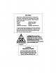
'A WARNING Exhaust gasses contain Carbon Monoxide, an odorless and colorless gas. Carbon Monoxide is poisonous and can cause unconsciousness and death. Symptoms of Carbon Monoxide exposure can include: -Oizziness - Throbbing in Temples -Nausea - Muscular Twitching -Headache - Vomiting - Weakness and Sleepiness - Inability to Think Coherently IF YOU OR ANYONE ELSE EXPERIENCE ANY OF THESE SYMPTOMS, GET OUT INTO THE FRESH AIR IMMEOIATELY. If symptoms persist, seek medical attention.
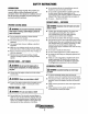
SAFETY INSTRUCTIONS INTRODUCTION • Do not operate with the air cleaner/silencer removed. Backfire can cause Severe injury or death. • Do not smoke or permit flames or sparks to occur near the fuel system. Keep the compartment and the engine/generator clean and free of debris to minimize the chances of fire. Wipe up all spilled fuel and engine oil. • Be aware - diesel fuel will·bum. Read this safety manual corefuUy. Most accidents are caused by failure to follow fundamental rules and precautions.
SAFETY INSTRUCTIONS BATTERY EXPLOSION A WARNING: Carbon monoxide (CO) Is an Invisible A WARNING: Battery explosion can cause injury odorless gas. Inhalation produces f1u~lIke symptoms, nausea 01 death! 01 death! • Do not smoke or allow an open flame near the battery being serviced. Lead acid batteries emit hydrogen, a highly explosive gas, which can be ignited by electrical arcing or by lit tobacco products.
TABLE OF CONTENTS Parts Identification ....................................................2 Introduction ................................................................3 Engine Adjustments (cont.) ......................................22 Injection Timing ................................................. 25 Warranty Procedures ............................................ 3 Remote Panel ....................................................... 3 Frequency Adjustment .......................................
PARTS IDENTIFICATION CONTROL PANEL ___FMFRf.:FNIr.V RADIATOR PRESSURE STOP SWITCH SA FUSE 'EXHAUST FAN COVER _...--l-.~-~-""t= RADIATOR THERMOSTAT .HOUSING FRONT LEFT SIDE 'FAN COVER FRONT PRESSURE CAP AIR INTAKE/SILENCER INJECTORS CONTROL PANEL START/STOP/ON SWITCHES INSTRUMENT GAUGES------£~~-.
INTRODUCTION This WES'IERBEKE Diesel Generator is a product of WES'IERBEKE's long years of experience and advanced technology. We take great pride in the superior durability and dependable performance of our engines and generators. Thank you for selecting WES'IERBEKE. In order to get the full use and benefit from your generator it is important that you operate and maintain it correctly. This manual is designed to help you do this. Please, read this .
INTRODUCTION SERIAL NUMBER LOCATION NOTE: A carbon monoxide warning decal has been provided by WESTERBEKE. Affix this decal in a visible position in the engine room. The engine and generator serial numbers and model numbers are located on a decal on the generator housing. Take the time to enter this information on the illustration of the nameplate shown below, as this will provide a quick reference when seeking technical information and/or ordering repair parts. ..
FUEL, ENGINE OIL AND ENGINE COOLANT ENGINE COOLANT FUEL WESTERBEKE recommends a mixture of 50% antifreeze and 50% distilled water. Distilled water is free from the chemicals that can corrode internal engine surfaces. A CAUTION: Only use unleaded fuel with an octane rating of 89 or higher. Leaded fuel will cause serious harm to your engine and violate your warranty. The antifreeze performs double duty.
GENERATOR CONTROL PANELS DESCRIPTION OF SWITCHES EMERGENCY STOP: The EMERGENCY stop switch on 1he side of the control box, is normally closed. When depressed, it will open the DC circuit to the control panel and shut the engine down. As the switch is not toggled it can be used when performing maintenance. This manually controlled series of WES1ERBEKE marine diesel generators is equipped wi1h toggle switches on 1he engine control panel and, optionally, at remote panels.
PREPARATIONS FOR INITIAL START-UP PRESTART INSPECTION • Be sure that in power systems with a neutral line that the neutral is properly grounded (or ungrounded) as the system requires, and that the generator neutral is properly connected to the load neutral. In single phase systems an incomplete or open neutral can supply the wrong line-toneutral voltage on unbalanced loads.
STARTING/STOPPING PROCEDURE THE STARTING SYSTEM Should the engine not start when the START switch is depressed for 10 to 20 seconds, release both switches and wait 30 seconds; repeat the procedure above and preheat longer. Never run the starter for more than 30 seconds. Westerbeke diesel generators use electric starters assisted by glow plugs for both nonnal and cold weather starting. The illustration below shows a cross-sectional view of one cylinder.
STARTING/STOPPING PROCEDURE STARTING UNDER COLD CONDITIONS Remote Stopping Procedure To stop the generator, depress the STOP switch which opens the normally closed B+ path for voltage to the engine's run circuit. The STOP switch must be held open until the generator comes to a complete stop and the green LED light goes out. . Make sure !he lubricating oil conforms with the ratings for the prevailing temperature. Check the table in the ENGINE OIL section in this manual.
GENERATOR BREAK-IN PROCEDURE DESCRIPTION After the first 10 hours of the generators operation, the load can be increased to the full-load rated output, then periodically vary the load. Although your engine has experienced a minimum of one hour of test operations at the factory to make sure accurate assembly procedures were followed and that the engine operated properly, a break-in time is required.
MAINTENANCE SCHEDULE A WARNING: Never attempt to perform any service while the engine is running. Wear the proper safety equipment such as goggles and gloves, and use the correct tools for each job. Disconnect the battery terminals when servicing any of the engine's DC electrical equipment. NOTE: Many of the following maintenance jobs are simple but others are more difficult and may require the expert krwwledge of a service mechanic.
MAINTENANCE SCHEDULE NOTE: Use the engine hour meter gauge to log your engine hours or record your engine hours by running time. SCHEDULED MAINTENANCE CHECK EACH DAY HOURS OF OPERATION 50 100 250 Coolant System 500 D EXPLANATION OF SCHEDULED MAINTENANCE 750 1000 1250 D Drain, flush, and refill cooling system with appropriate antifreeze mix. Electric Fuel (ift Pump D DC Alternator D D D D D D *Fuellnjectors D Periodically check the wiring connections ..
FUEL SYSTEM DIESEL- FUEL ENGINE FUEL FILTER Use No.2 diesel fuel with a cetane rating of 45 or higher. Do not use kerosene or home heating fuel. Periodically check the fuel connections and the bowl for leakage. Replace the filter element after the first 50 hours then follow the MAINTENANCE SCHEDULE. FUEL FILTERS The fuel injection pump and the fuel injectors are precisely manufactured and they must receive clean diesel fuel, free from water and dirt.
COOLING CIRCUIT DESCRIPTION When the engine is started cold, external coolant flow is prevented by the closed thennostat (although some coolant flow is bypassed around the thermostat to prevent the engine from overheating). As the engine warms up, the thermostat gradually opens, allowing full flow of the engine's coolant to flow unrestricted to the external portion of the cooling system. Westerbeke diesel engines are designed and equipped for fresh water cooling.
ENGINE COOLING CIRCUIT THERMOSTAT TO COOLANT ; RECOVERY TANK FROM COOLANT RECOVERY TANK COOLANT EXPANSION A thermostat, located near the front of the engine, controls the engine's coolant temperature, as the coolant continuously flows through the engine's closed cooling system.. When the engine is first started and the thermostat is closed, engine coolant by passes the thermostat to provide proper circulation and cooling via a by-pass hose located between the circulating pump and below the thermostat.
ENGINE LUBRICATING OIL LUBRICATION DIAGRAM 2. Replacing the Oil Filter. When removing the used oil filter, you may find it helpful and cleaner to punch a hole in the upper and lower portion of the old filter to drain the oil from it into a container before removing it. Thls helps to lessen spillage. A small style automotive filter wrench should be helpful in removing the old oil filter.
REMOTE OIL FILTER (OPTIONAL) To install, simply remove the engine oil filter and thread on WESTERBEKE'S remote oil filter kit as shown. Always install this kit with the oil filter facing down as illustrated. INSTALLATION This popular accessory is used to relocate the engine's oil filter from the engine to a more convenient location such as an engine compartment. Contact your WESTERBEKE dealer for more information.
STARTER MOTOR DESCRIPTION The starter is a new type, small, light-weight and is called a high-speed internal-reduction starter. The pinion shaft is separate from the motor shaft; the pinion slides only on the pinion shaft. A reduction gear is installed between the motor shaft and a pinion shaft. The pinion sliding part is not exposed outside the starter so that the pinion may slide smoothly-without becoming fouled with dust and grease. The motor shaft is supported at both ends on ball bearings.
STARTER MOTOR EMERGENCY START ·A WARNING: When perfonning these procedures, Corrosion to the starter brushes and/or the solenoid contacts can cause the sporadic problem of the engine starting one time but not another. If corrosion is the problem, the starter will need to be rebuilt. It is however, sometimes possible to get started by taping the starter lightly with a small hammer. With the battery switch off and no ignition,.
ENGINE TROUBLESHOOTING Note: The engine s electrical system is protected by a 20 amp manual reset circuit breaker located on a bracket at the rear of the engine. The following troubleshooting table describes certain problems relating to engine service, the probable causes of the problems, and the recommendations to overcome these problems. Problem PREHEAT switch depressed: no panel indications; fuel solenoid or electrical fuel pump Probable Cause Verlflcation/Remedy 1. Battery Switch not on. 1.
ENGINE TROUBLESHOOTING Problem Generator engine stops. Probable Cause VerificationJRemedy 1. Fuel feed pump strainer is dirty. 1. Clean strainer (32 KW only). 2. Switches and/or wiring loose or disconnected. 2. Inspect wiring for short circuits and loose connections. Inspect switches for proper operation. 3. Fuel starvation. 3. Check fuel supply, fuel valves, fuel feed strainer. 4. 20 Amp circuit breaker tripping. 4. Check for high DC amperage draw during operation.
ENGINE ADJUSTMENTS NOTE: WESTERBEKE recommends that the following enginE! adjust~ ments be performed by a competent engine mechanic. The information below is provived to assist the mechanic. DRIVE BELT ADJUSTMENT (FAN BELT) TORQUING THE CYLINDER HEAD BOLTS For your safety, WESTERBEKE generator models come . equipped with belt guards that cover over the belt(s) on the front of the engine. ("Out of sight - out of mind." The belt guard is NOT installed for that purpose.
ENGINE ADJUSTMENTS VALVE CLEARANCE ADJUSTMENT Re-install the glow plugs (use anti-seize compound on the threads) and assemble the rocker cover and rocker cover bolts. See TIGH1ENING TORQUE SCHEDULE in this manual. NOTE: Retorque the cylinder head bolts before adjusting the engine's valves. See IDRQUING THE CYLINDER HEAD BOLTS. ENGINE COMPRESSION A WARNING: Adjust the valve clearance when the Check the compression pressure.
ENGINE ADJUSTMENTS GLOW PLUGS OIL PRESSURE The glow plugs are wired through the preheat solenoid. When PREHEAT is pres~ed at the control panel this solenoid should "click" on and the glow plug should begin to get hot. To test the oil pressure, remove the oil pressure sender, then install a mechanical oil pressure gauge in it's place, After warming up the engine; set the engine speed at 1800 rpm and read the oil pressure gauge.
ENGINE ADJUSTMENTS NOTE: WESTERBEKE recommends that the following engine adjustments be performed by a competent engine mechanic. The information below is provided to assist the mechanic. Injection Pump Timing Adjustment (Spill Timing) INJECTION PUMP. If your engine's fuel injection timing is not properly adjusted, the engine will not operate properly, and may be difficult to start. Have the injection pump delivery rate checked by a well-established fuel injection shop.
ENGINE ADJUSTMENTS GENERATOR FREQUENCY ADJUSTMENT (HERTZ) FUEL RUN SOLENOID Once the diesel generator set has been placed in operation, there may be adjustments required for engine speed (Hertz) during the engine's break-in period (first 50 hours) or after this period. A no-load voltage adjustment may also be required in conjunction with the engine's speed adjustment These are not warrantable adjustments as they relate to normal break-in and maintenance.
ENGINE ADJUSTMENTS ELECTRONIC GOVERNOR (OPTIONAL)· 4. Back-offthe 1 7/16" jam nut and unscrew the actuator. 5. Apply a small amount of teflon sealant to the replacement actuator and screw the actuator into the engine's mounting boss. Maintain the same distance between the actuator and the engine mounting surface as previously measured Secure the actuator's position with the jam nut. (The standard distance is 13/16" to 7/8"). 6. Reconnect the actuator wires and test the unit.
7.6KW BTDR GENERATOR ONLY ALTERNATORS TESTING/TROUBLESHOOTING SEE WIRING DIAGRAM FOR WIRE CONNECTIONS TO OPTIONAL ALTERNATORS 50 AMP ALTERNATOR NOTE: FOR CORRECT WIRING HARNESS CONNECTIONS TO THE ALTERNATOR, REFER TO THE WIRING DIAGRAMS IN THIS MANUAL. DESCRIPTION VOLTAGE REGULATOR The following information applies to the standard alternators that are supplied with WESTERBEKE'S Engines and Generators.
ALTERNATORS TESTING/TROUBLESHOOTING PRELIMINARY INSPECTION Before starting the actual alternator and voltage regulator, testing the following checks are recommended. 1. Make certain your alternator is securely mounted. 2. Check the drive belts for proper tension. Replace the ~lt if it is worn or glazed. 3. Check that all terminals, connectors and plugs are clean and tight. Loose or corroded connections cause high resistance and this could cause overcharging, undercharging or damage to the charging system.
ALTERNATORS TESTING/TROUBLESHOOTING 5. If no reading is obtained, an open exists in the alternator-excitation lead or in the excitation circuit of the regulator. Disconnect the lead from exc terminal R. Connect the positive multimeter probe to the excitation lead and the negative inultimeter probe to ground terminal E. If the multimeter now indicates an approximate battery voltage, the voltage regulator is defective and must be replaced.
DC CIRCUIT/BATTERY BATTERY CHARGING TESTING THE CIRCUIT The DC Circuit functions to start, operate and stop the generator's engine. The circuit is best understood by reviewing the DC WIring Diagram and Wiring Schematic. The engine's DC wiring is designed with three simple basic circuits: start, run and stop. If the battery is not charging, check the fuse. To test the circuit, remove the fuse and test with a voltmeter between the fuse holder connection and the ground.
CONTROL PANEL TROUBLESHOOTING MANUAL STARTER DISCONNECT (TOGGLE SWITCHES) NOTE: The engine control system is protected by a 20 amp manual reset circuit breaker located on the engine as close as possible to the power source. Problem Verification/Remedy Probable Cause PREHEAT depressed, no panel indications fuel solenoid, electric fuel pump and preheat solenoid not energized. START SWITCH DEPRESSED, no starter engagement. NO IGNITION, cranks, does not start. NOT CHARGING BATTERY 1. Oil Pressure switch.
7.6BTDR WIRING QIAGRAM #44743 .eJJ!Q.S. ALIE RNA TOR 5QA - IZYDC WA TER T ~MPERATUR[ SWITCH ll!l.I2IR ~~ = ~ = 0 n WATER TEMPEBATURE = Q W . " VIO ~. r, 0 E~~ ~ (( OGND( E 0 = . ;:; @D:: ;;:;.~e ., ~ FUEL §QLEHOIQ Q ...... CURRENT T I MER :: : PREHEAT SOlENO I D tl2 RED ~ . 0 ~ ~ ~ © tURED ,,~'"" -po torT GXD ~ '14 RED/VIO 0 [UEL SQLENQID SWITCH II~ 0 . > BATTERY SWITCH r~~----- -----'~ ~J tl2 RED ~~ IIZY[lIRED START"ER MOTOR ~ AUX.
7.68TOR WIRING SCHEMATIC #44743 BATTERY i BATTERY I SWITCH CIRCUIT BREAKER r -________ 12 VDe STARTER ~I~-~~or_--------------~~--~I__4--r_--l~--_1~--------~ I STARTER I ISOlENOIOI I I GLOWPLUGS I 1 EMERGENCY I I I STOP I SWITCH AL TERNATOR o KI-START K2-RUN -+__~~__~ ~1~B~I-'I----------~--~----------~3~O ~81~______ WATER TEMP. SWITCH 8A Oil PRESS_ SWI TCH FUEl SOL.
5.0BCDR WIRING DIAGRAM #44742 P¥tMs = ~D - r!~ llKQU SATTERY CIIARGER OUTPUT ~ = ~ = GENERATOR WATER TEMPERATURE SWI TCH WATER TEMPERATURE ~ ~ lO! ;; 1 J- ;; N ., T.I4I1LI "."m c • 14 RED/VIO ; -v ! c - CD BATTERY SWITCH ,~~-- - - - - I 12 VDC :-~ ~l = tl2 RED n C>o lO! ; SWEWITO 30A FUSE aAT.~ rUSE lOA ~ .~ a:: FUEl SOLENOIP Q toCURRENT TIMER ~ !& CD ... ;;;H -, 0 FUEL SOLEHOIQ OIL PRESSURE SWITCH ~ . II~ k ~. > OIL eHE§§UBE .
5.0BCDR WIRING SCHEMATIC #44742 BA TTERY 12 VDC i BATTERY I SWI TCH CIRCUIT BREAKER STARTER .-___---,'' '-CC- :lor--_ _ _ _ _ _ _-<>-_...,r--j- -1----:-1- . -__-{ I STARTER I ISOLENO I DI I I +-____________~_r~-~-~-~l----~ 1 E~ERGENCY r I I GLOWPLUGS I PREHEAT I I STOP I SWITCH 'SOLENOID1 I I 30A KI-START XI-RUN ~T~8~1_~I_ _ _ _ _ _ _~_~_ _ _ _ _~3~O~1-8~1~_ _ _ _ _ _~ WATER TENP.
REMOTE STOP/START PANEL WIRING DIAGRAM #44329 STOP SWITCH 2 5 PREHEAT SWITCH REMOTE CONTROL PANEL (REAR VIEW) 1"-"-"-"-"-"-"-"-"-"-"-"-"-"-"-"-"-: . I START SWITCH' STOP SWITCH .t 16 REDIVl 116 BlK 116 RED/IIHT 416 WHT 000 IIG RED PREHEAT. SWITCH START o SWITCH I I I @@@ @0J® «16 WHTIRED L.::;.._ _:;;.J .: MALE CABLE CONNECTOR REAR VIEW 'I~ RED Cl6 yEtIRED i :..- .. _ .. _ .. _ .. _ .. ...:: .• _ . r . - .. __•• _ P.N. .• _ .. _ •• _ .. _ •. _ •. _ .. _ •.
GENERATOR INFORMATION USE OF ELECTRIC MOTORS Generator Maintenance The power required to start an electric motor is considerably more than is required to keep it running after it is started. Some motors require much more current to start them than others. Split-phase (AC) motors require more current to start, under similar circumstances, than other types. They are commonly used on easy-starting loads, such as washing . machines, or where loads are applied after the motor is .
7.6KW BT· GENERATOR TROUBLESHOOTING This troubleshooting chart is designed to give insight into problems which may be encountered with BT brushless generators operating on compound transformer regulation. Owing to the simplicity of the equipment and controls, troubleshooting is relatively easy, once the relationship between cause and effect is understood. WESTERBEKE recommends that the troubleshooting and repair of .
7.6KW BT GENERATOR SINGLE PHASE . DESCRIPTION Circuit Breaker This generator is a four-pole, brushless, self-excited generator A circuit breaker is installed on all WES1ERBEKE generawhich requires only the driving force of the engine to protors. This circuit breaker will automatically disconnect generator power in case of an electrical overload. The circuit duce AC output.
7.6KW BT GENERATOR SINGLE PHASE NO-LOAD VOLTAGE ADJUSTMENT c. After the no-load hertz adjustment is made, the no-load voltage may need to be readjusted. In most cases, if the generator was producing the correct no-load voltage at the previous hertz setting, it would be correct at the changed hertz setting. In the event it needs adjustment, adjust the shim thickness under the laminated steel bar of the transformer. 60 hertz: no-load voltage, 121 - 124 volts. 50 hertz: no-load voltage, 234 - 238 volts. d.
7.6KW BT GENERATOR SINGLE PHASE INTERNAL WIRING FOR 12 SIDD BT GENERATOR r---- -- --------. I I 1 A : , B I , C B :I 1>1- I 4 3, . I I 2 IL _____________ J, , ORANGE + DC GREEN r-------, ,r-------., C I ' i !~!: i~i! ! ; I 3 IL I I ______ J I w D AC BLACK 9l r---+---1~ i' 6 1. . . . 2. . . . 3 ===;7'..c= I !~ I r WHT/ BlK L~l~~!--I--:- . . J ~ " , ~ o L-.._ _....I G AC 0 ~ • @ _ WHT/GREEN • U D -I
7.6KW BT GENERATOR SINGLE PHASE BRIDGE RECTIFIER The bridge rectifier is supplied AC voltage from the auxiliary windings in the generator stator «(::-3) and the compound transformer (D-3). The AC voltage measured across the AC terminals of the rectifier during engine operation is as follows: 120 Volts NIL FIL ; 120/240 Volts NIL FIL 17 - 44 Volts AC .
7.6KW BT GENERATOR SINGLE PHASE The diodes can be easily checked in place with the use of a common automotive 12-volt high beam headlight bulb, some jumper leads and the generator's 12 volt starting battery. A short or an open in a diode can easily be found with the above without having to unsolder and isolate each diode to check it with an ohmmeter. EXCITER ROTOR/FIELD Auxiliary windings group a, b and c. Locate the three terminal points on the exciter rotor for these auxiliary winding groups.
7.8KW BT GENERATOR SINGLE PHASE MEASURING RESISTANCE A three connection voltage connection tenninal was added to this circuit located just below the AC tenninal block at the lower left. Isolate the three numbered #1, #2, and #3 red and white-striped wires coming onto each of the three tenninals. Lift the black and white-striped leads and the green and white-striped leads off of their connections on the AC tenninal block.
SPECIFICATIONS • 7.6KW ITO GENERATOR ENGINE SPECIFICATIONS Engine Type Aspiration Governor Combustion Chamber Bore & Stroke Piston Displacement Rring Order Direction of Rotation Compression Ratio Dimensions Weight Fuel Consumption Inclination Generator Power Take Off ELECTRICAL SYSTEM Diesel, four-cycle, three-cylinder, fresh water-cooled, vertical in-line overhead valve mechanism (11 Hp at 1800 rpm maximum). Naturally aspirated Centrifugal type Swirl type 2.99 x 2.76 inches (76 x 70 mm) 59.
5.0KW Be GENERATOR SINGLE PHASE DESCRIPTION Circuit Breaker The BC generator is a brushless, self-excited generator which requires only the driving force of the engine to produce an AC output. The stator houses two sets of windings; the main stator windings and the exciter windings. When the generator is started, residual magnetism in the four rotating poles induces a current in the stator which then generates an even larger current in the exciter windings.
5.0KW BC GENERATOR TROUBLESHOOTING This troubleshooting chart is designed to give insight into problems which may be encountered with BT brushless generators operating on compound transformer regulation. Owing to the simplicity of the equipment and controls, troubleshooting is relatively easy, once the relationship between cause and effect is understood.
5.0KW Be GENERATOR SINGLE PHASE DUAL EXCITER NO-LOAD VOLTAGE ADJUSTMENT NOTE: When changing Hertz produced by the generator, an engine speed adjustment at the throttle arm linkage must be made. The AC output connections on the terminal blocks must be selected for the voltage and Hertz to be produced The Hertz plug connection at the capacitor must be changed for 50 Hertz (#5) or 60 Hertz (#6). Thejrame ground wire must be nwved when changing from 115 volts, 50 Hertz to 230 volts, 50 Hertz.
5.0KW BC GENERATOR SINGLE PHASE SINGLE EXCITER NO-LOAD VOLTAGE ADJUSTMENT ·A WARNING: 00 not attempt to make a no-load 1. Remove the louvered metal plate, at the back of the generator, covering the AC terminal connections and the capacitor(s). voltage adjustment while the generator is operating. The capacitor can produce a 400-500 volt charge. Touching any wiring can produce a severe electrical shock.
5.0KW Be GENERATOR SINGLE PHASE Testing the Battery Charging Circuit INTEGRAL CONTROLLER (I.C.) The Integral Controller (I.C.) is an encapSUlated, solid-state unit that supplies a DC charging voltage to the generator's starting battery while the generator is opening. Charging Voltage: 13.0 - 14.0 volts DC Charging Amperage: 0 - 10- amps DC A separate group of stator windings supplies AC voltage to a bridge rectifier which converts the AC current to supply the I.C. unit. The I.C.
5.0KW BC GENERATOR SINGLE PHASE Ballast Resistor 0.5 Ohm Unplug any other connections from the capacitor(s) noting their position on the capacitor. Place one lead of the ohmmeter on plug connection #9 and the other lead on plug connection #50 Hertz. Measure the resistance value of the exciter windings. Check to make sure there is no continuity to the ground/generator case from either of the two leads.
5.0KW Be GENERATOR SINGLE PHASE 7. During 12 volt excitation, output voltage ranges are as "follows: Dual Dual Single Capacitor Exciter Capacitor 22 - 26VAC 24 - 28 VAC 12 -14 VAC a. A slight rise in the output voltage with the loading of the engine and/or a growling noise from the generator end will indicate a fault in the main stator windings. b. No rise or very slight rise in the output voltage will indicate a fault in the exciter windings. c.
5.0KW Be GENERATOR SINGLE PHASE Testing Component Resistance Values Rotating Field/Auxiliary Windings and Diodes Two sets of windings are found in the rotor assembly. An AC voltage is produced in two groups of windings as the rotor turns at rated rpm. The AC voltage passes through each of the two diodes mounted on the isolated fixture just before the rotor carrier bearing. The AC sine wave is changed to a DC and this DC voltage is passed through the two groups of. .
SPECIFICATIONS - 5.0KW BCDBR GENERATOR ENGINE SPECIFICATIONS Engine Type Aspiration Governor Combustion Chamber Bore &Stroke FUEL SYSTEM Diesel, four-cycle, three-cylinder, fresh water-cooled, vertical in-line overhead valve mechanism (9.2 Hp at 1800 rpm maximum). Naturally aspirated Centrifugal type Swirl type General Fuel Fuel Injection Pump Fuel Injection liming (spill timing) Nozzle Fuel Filter Air cleaner Air Flow (engine combustion) 2.76 x 2.76 inches (70 x 70 mm) Piston Displacement 49.
GenRemote CALIBRATION NOTE: THIS DATA APPLIES ONLY TO THE OPTIONAL GenRemote CONTROLS . The unit consists of a Power Logic Module, Display Panel and six conductor shielded Display Cable. The shielded cable links the display to the module and can be up to 300 feet long. Two display panels can be daisy chained to one (1) module output. The module supports two display cable outputs allowing for a total of four (4) displays per module.
GenRemote CONTROL STATION IMPORTANT! The generator must be running and the system fully operational before the . calibration mode can be accessed . Enter the Calibration Mode: Press and holding the Mode Button for 10 seconds. Entry is indicated when the hundreds place decimal of the 3-digit, 7-segment display turns on. Calibration Button Functions Mode Button: Press and hold. the mode button to enter the calibration mode.
GenRemote WIRING DIAGRAM Figure - 2a Westerbeke Wiring for Westerbeke Hamess and Plug ~. Black Ground . LAND BASED UNIlS / U M P ESSTOEXH • ESS .......... W'hIte/Red STOP START PreHeat • ........ 000 000 • Exhaust OIL Press \Nesferbeke PI Water Temp BlACK WHIl'E/RED ORANGE GROUND STOP OIL REDMOLET ESS WHIlJ: PREHEAT YELLOW H2O GenRemoIe Teomlna18lock feJmlnals I thru e To Westerbeke Wire Hamess and Plug J VELLOW/RED START dlS SS] A.,.
GenRemote INSTALLATION DIAGRAM Note: GenRemote uses engine oil pressure and AC voltage to recognize the engine is running. Without AC input the generator will run and GenRemote will only monitor the Battery, Water Temp and Oil Pressure. No AC readings will be displayed and the Run Indicator will not tum on.
GenRemote SPECIFICATIONS' DC DC . DC DC OPERATING VOLTAGES ................................................................. 12 OR 24 VDC CURRENT RECUIREMENT--MoDULE .............................................................. 50 MA CURRENT REQUIREMENT--DISPLAY .............................................................. 20 MA CURRENT EACH ADDITIONAL DiSPLAy ............................................................. 15 MA AC VOLTAGES ••••••••••••••••••••••••••••.•••••••••••••••••••••••.•.
POWER TAKE OFF SYSTEMS POWER TAKE OFF ADAPTER A power take off adapter can be attached to the generator backend. This adapter allows access to the full power of the ~~ for a variety of hydraulic and electrical accessories. Contact your WESTERBEKE COMMERCIAL GENERATOR SUPPUER for additional information . POWER TAKE OFF ADAPTER .
STANDARD AND METRIC CONVERSION DATA LENGTH-DISTANCE Inches (in) x 25.4 = Millimeters (mm) x .0394 = Inches Feet (ft) x .305 = Meters (m) x 3.281 = Feet Miles x 1.609 = Kilometers (km) x .0621 = Miles DISTANCE EQUIVALENTS 1 Degree of Latitude = 60 Nm = 111.120 km 1 Minute of Latitude = 1 Nm = 1.852 km VOLUME Cubic Inches (in3) x 16.387 = Cubic Centimeters x .061 =in3 Imperial Pints (IMP pt) x .568 = Liters (L) x 1.76 = IMP pt Imperial Quarts (IMP qt) x 1.137 = Liters (L) x.
-- SUGGESTED SPARE PARTS CONTACT YOUR WESTERBEKE DEALER FOR SUGGESTIONS AND ADDITIONAL INFORMATION THERMOSTAT KIT FUEL SYSTEM HARDWARE KIT FILTER CARTRIDGE Engines & Generators 62
Engines & Generators WMDW107301106