OPERATOR'S MANUAL l,WESTERBEKE BCD 4.4KW and BCD 6.0KW MARINE DIESEL GENERATOR SETS Publication # 37144 Edition Two May 1988 j'-.
SAFETY PRECAUTIONS The following symbols appear in this manual to call attention to and emphasize conditions potentially dangerous to the operator. • Use Extreme Care When Handling Engine Fuel (A constant danger of explosion or fire exists) Do not fill fuel tank(s) while the engine is running. Do not smoke or use an open flame near the engine or the fuel tank. IWARNINGI The above symbol is used in the manual to warn of possible serious personal injury or loss of life.
IMPORTANT PRODUCT SOFTWARE DISCLAIMER Product software of all kinds, such as brochures, drawings, technical data, operator's and workshop manuals, parts lists and parts price lists, and other information, instructions and specifications provided from sources other than Westerbeke, is not within Westerbeke's control and, accordingly, is provided to Westerbeke customers only as a courtesy and service.
FOREWORD Thank you for selecting a Westerbeke marine product for your use. We at Westerbeke are pleased to have you as a customer. Read this manual carefully and observe all safety precautions included throughout.
TABLE OF CONTENTS Section .........................................................................Page GENERAL ........................................................................... 5 BCD 4.4KW GENERAL SPECiFiCATIONS ...................... 10 BCD 4.4KW SYSTEM SPECIFICATIONS ........................ 11 BCD 6.0KW GENERAL SPECiFiCATIONS ...................... 14 BCD 6.0KW SYSTEM SPECIFICATIONS ........................ 15 INSTALLATION CHECKS .................................................
TABLE OF CONTENTS (CONTINUED) LAY-UP & RECOMMISSIONING ......................................75 TABLE OF STANDARD HARDWARE TIGHTENING TORQUES ..................................................79 TABLE OF TIGHTENING TORQUES ...............................80 SPARE PARTS ..................................................................81 INDEX ................................................................................
GENERAL Introduction This manual contains the equipment operating procedures as well as additional information needed to help the operator keep the marine equipment in proper working order. Study and follow the instructions carefully. A planned maintenance program is included in this manual; adhering to the program will result in better equipment performance and longer equipment life.
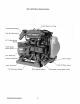
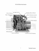
BCD 4.4KW Marine Diesel Generator Fresh Water Fill Cap 45 0 Exhaust Elbow i Fuel Run Solenoid AC .Fr~shJII(~ter Block Drain Zinc Anode Lube Oil Drain Hose Lube Oil Pressure Sender Westerbeke Generators Oil Pressure Switch 6 Exchanger Fresh Water Drain.
BCD 4.
BCD 6.
BCD 6~OKW Marine Diesel Generator Fresh Water ~AirBleea FreshWater ·c i rcufaiIn9~f:i~iiii?"' Sea Water ~eat Exc::hanger.
BCD 4.4KW MARINE DIESEL GENERATOR SET GENERAL SPECIFICATIONS Engine Type Diesel, four-cycle, two-cylinder, fresh water-cooled Vertical, in-line overhead valve mechanism (8.6 hp at 1800 rpm, maximum). Combustion Chamber Swirl type Bore & Stroke 2.68 x 3.07 inches (68 x 78 mm) Piston Displacement 37 cubic inches (0.606 liters) Firing Order 1-2 Direction of Rotation Clockwise, when viewed from the front Maximum Torque (at 1800 rpm) 33 Ib-ft (4.
BCD 4.4KW SYSTEM SPECIFICATIONS FUEL SYSTEM General Open flow - totally self-bleeding Fuel No.2 Diesel (cetane # 45 or better) Injector Pump In-line plunger type (Bosch M type) Injectors Pintle type Lift Pump 12-Volt DC; lift capacity 6 ft (1.8 m) Air cleaner Metal screen type - cleanable Air Flow (engine combustion) 19.2 cfm (0.544 cmm) COOLING SYSTEM General Fresh water-cooled block, thermostatically-controlled with heat exchanger.
BCD 4.4KW SYSTEM SPECIFICATIONS ELECTRICAL SYSTEM Starting Battery 12-Volt, 30 A-H, (-) negative ground (recommended) (45 A-H in cold areas) Battery Capacity 90 - 125 (Ampere-Hours) Starter 12-Volt, 1.2 'r
BCD 4.4KW SYSTEM SPECIFICATIONS NQIE.: Increase air supply 15% for 50 Hertz operation (1500 rpm). Engine Combustion Air Requirements, (60 Hertz), at 1800 rpm 19.2 cfm (0.544 cmm) TUNE-UP SPECIFICATIONS Injector Pressure 2275 psi +142 psi -0 psi .
BCD 6.0KW MARINE DIESEL GENERATOR SET GENERAL SPECIFICATIONS Engine Type Diesel, four-cycle, three-cylinder, fresh water-cooled Vertical, in-line overhead valve mechanism (12 hp at 1800 rpm, maximum). Combustion Chamber Swirl type Bore & Stroke 2.56 x 3.07 inches (65 x 78 mm) Piston Displacement 47.4 cubic inches (0.776 liters) Firing Order 1-3-2 Direction of Rotation Clockwise, when viewed from the front Maximum Torque (at 1800 rpm) 42 Ib-ft (6.2 kg-m) Compression Ratio 9.
BCD 6.0KW SYSTEM SPECIFICATIONS FUEL SYSTEM General Open flow - totally self-bleeding Fuel No.2 Diesel (cetane # 45 or better) Injector Pump In-line plunger type (Bosch M type) Injectors Pintle type Lift Pump 12-Volt DC; lift capacity 6 ft (1.8 m) Air cleaner Metal screen type - cleanable Air Flow (engine combustion) 24.6 cfm (0.697 cmm) COOLING SYSTEM General Fresh water-cooled block, thermostatically-controlled with heat exchanger.
BCD 6.0KW SYSTEM SPECIFICATIONS ELECTRICAL SYSTEM Starting Battery 12-Volt, 26 A-H, (-) negative ground (recommended) (35 A-H in cold areas) Battery Capacity 90 - 125 (Ampere-Hours) Starter 12-Volt, 1.2KW, reduction type, solenoid-mounted DC No-Load Current 90 Amp (max.) at 11.5 Volts. DC Cranking Current (engine cold) 175 - 200 Amps (engine cold) DC Charger Integral controller 0 - 10 Amps 13 -14 Volts DC AC GENERATOR General Brushless, four-pole, revolving field.
MITE: Increase air supply 15% for 50 Hertz operation (1500 rpm). Engine Combustion Air Requirements, (60 Hertz), at 1800 rpm 24.6 cfm (0.
INSTALLATION CHECKS General Since the crafts in which Westerbeke generators are installed vary in design, installation procedures will vary according to your craft's specific design. The intent of this section is not to advise boatyards or installers on procedures already well-developed and well-understood.
Rigging and Lifting The generator is fitted with lifting eyes. Rope or chain slings capable of supporting the generator's weight should be attached to the eyes and the generator lifted by means of tackle attached to these slings. The lifting eyes have been designed to carry the full weight of the generator; therefore, auxiliary slings are not required or desired. CAUTION Slings must not be so short as to place significant stress on the generator's lifting eyes.
Generator Mounting - Location The complete generator unit is mounted on lightweight rails by means of four flexible isolator mounts that help prevent the transfer of vibration from the generator to the rails. Each generator mounting rail has several 1/2-inch bolt holes so bolts can be employed to properly secure the generator to its mounting platform. These holes are on 15 inch mounting centers.
Exhaust System IWARNINGI Although diesel fuel is not as dangerous as gasoline, precautions should be taken to guard against CARBON MONOXIDE GAS. Carbon monoxide is a dangerous gas that can cause unconsciousness and is potentially lethal. Some of the symptoms or signs of carbon monoxide inhalation or poisoning are listed below.
Exhaust Back-Pressure The exhaust discharge hose must be of adequate size and minimal run to prevent excessive exhaust back-pressure. Exhaust back-pressure should be checked before a generator is put into service. (Refer to the illustration.) Excessive back-pressure will affect the engine's performance and the generator's power output. To measure for back-pressure, use a mercury manometer, a pressure gauge, or a water column. A boatyard or marine mechanic should have a manometer or a pressure gauge.
P"L"PP~R Dry stack-type exhaust systems (shown to the right) must be attached to the generator engine's exhaust manifold by means of a flexible connector pipe. This system must be properly supported and insulated to prevent water from entering into the engine's cylinders. Provisions must be made for discharging the engine's cooling sea water.
Exhaust Elbow Installation The Westerbeke Corporation offers a 45°and 900 exhaust elbow as well as an exhaust riser you can install on your propulsion engine. Refer to the instructions below when installing the exhaust elbow purchased for your generator. 1. Coat only one side of the exhaust gasket with *"High Tack" adhesive sealant. Place this coated surface against the exhaust manifold's exhaust port flange (the gasket should stick to the flange without falling off). 2.
Fuel System The fuel system should be installed in such a manner as to allow the engine-mounted fuel lift pump to pump to maintain a positive inlet pressure to the injection pump under all operating conditions. The minimum size of the fuel supply line and fuel return line is 1/4 inch, inside diameter, and there should be a primary fuel filter installed between the fuel tank and the fuel lift pump.
Sea Water Intake System Make sure the intake system (sea water cooling system) is in proper order. Check that the hull inlet, sea cock and strainer are unobstructed. Sea cocks and strainers should be at least one size greater than the inlet thread of the sea water pump. The strainer should be of the type that may be withdrawn for cleaning while the vessel is at sea and should be mounted below the water line to ensure self-priming.
DC Electrical Connections A common ground for the negative (-) DC terminal connection is found at the bell housing of the generator, next to the starter, in the form of a threaded grounding stud. The battery ground should be connected at this stud. Connect the battery's positive ( +) connection to the starter solenoid tagged for this connection. CAUTION To avoid an overcharging condition, and a possible equipment failure, DO NOT disconnect the DC battery source while the engine is running.
Batteries Make sure the positive ( + ) battery connection is connected to the battery connection of the starting solenoid. The negative (-) battery connection should be connected to the system ground (the engine block). When servicing the battery or checking the electrolyte level, wear rubber gloves, a rubber apron, and eye protection. Battery acid may splash on the skin or into the eyes inadvertently when removing the electrolyte caps.
DESCRIPTION OF INSTRUMENT PANEL o o PREHEAT ~ .... 1 ."' .~'. ,\ @ STOP \..... _..... ..: . o o General The manually-operated series of Westerbeke generators is equipped with toggle switches and, optionally, remote panels. The Standard Instrument Panel (shown above) includes two gauges which indicate water temperature in degrees Fahrenheit (WATER oF) and oil pressure in pounds per square inch (OIL PSI).
Remote Operation For starting and stopping the generator at a remote location, the same three switches are used. The PREHEAT and START switches are connected in parallel with the local panel's switches and serve the same functions as in the local panel. The STOP switch is connected in series with the local panel's STOP switch and serves the same function as in the local panel.
Description of Starting System Westerbeke diesel engines use electric starters assisted by glow plugs for both normal and cold weather starting. The figure below shows a cross-sectional view of one cylinder. The glow plug is located in the combustion chamber so that its tip is in the injector nozzle's spray path. When the glow plug is energized by the PREHEAT button, the plug glows red at the tip and assists in igniting the fuel. The result is a rapid start with less wear on the starter.
PREPARATION FOR STARTING This section of the manual provides the operator with preparation, initial starting, break-in, starting (cold or warm), and stopping procedures. Follow the procedures as presented, for the conditions indicated, and your Westerbeke engine set will give you reliable performance and long service life. Fill your engine with oil up to or near the upper limit on the dipstick (the installation angle may have an effect on the dipstick reading).
STARTING PROCEDURE 1. Depress and hold the PREHEAT switch. Preheat according to the following chart: 2. While still depressing the PREHEAT switch, depress the START switch. As soon as the engine runs, release the START switch but continue to hold the PREHEAT switch depressed for an additional 2 to 3 seconds. This allows the engine to build up enough oil pressure to close the oil pressure shutdown switch and allow the engine to continue to run.
STOPPING PROCEDURES 1. Remove the AC electrical load from the generator and allow the generator to run for 3 to 5 minutes so the engine can stabilize its operating temperatures. 2. Depress the STOP switch and hold it until the generator comes to a complete stop. Now release this switch.
Starting Under Normal Conditions Follow the procedure below for normal starting of the generator: 1. Make sure there is sufficient fuel on board. Keep fuel tank(s) as full as possible. Check the fuel filters and water separators for the presence of contaminants and/or water. Drain and clean them as needed. 3. Check the coolant level in the plastic recovery tank. Add coolant solution as needed. NOTE: Excessive loss of coolant from the plastic recovery tank indicates a cooling system leak.
FUEL SYSTEM Diesel Fuel Use No. 2 diesel fuel with a cetane rating of 45 or higher. Never use kerosene or home heating oil since these fuels do not have the same lubricating properties as No.2 diesel fuel. In cold weather particularly, water vapor is produced by condensation when air is present in the fuel tank. Keep fuel tank(s) full and completely free of dirt and water. Fuel Filters A primary fuel filter of the water entrapment type must be installed between the fuel tank and the engine.
Priming the Fuel System The Westerbeke self-bleeding fuel system is semiautomatic in operation. The self-bleeding feature of the fuel system allows for easy servicing of the fuel filters. Simply remove the and replace the filter elements (take care in catching any fuel that may drain out of the fuel filtering assemblies) as described in the "Replacing the Fuel Filter Elements" section below.
Fuel Injection Pump The illustration below shows the BCD 6.0KW's fuel system. The BCD 4.4KW fuel system's differs in that it has one less fuel injector and injector pump plunger. The fuel injection pump, located to the right, is one of the most important components of the diesel engine and, therefore, calls for the utmost caution in handling. Furthermore, the fuel injection pump has been thoroughly bench-tested and should not be tampered with.
DC ELECTRICAL SYSTEM Engine 12-Volt DC Control Circuit The Westerbeke BCD 4.4KW and BCD 6.0KW generators have a 12-Volt DC electrical control circuit, as shown on the wiring diagrams which follow on pages 42 and 45. Refer to these diagrams when troubleshooting or servicing electrical components on the engine. CAUTION To avoid damage to the battery charging circuit, never shut off the engine battery switch while the engine is running.
Testing the Battery Charging Circuit NOTE: This circuit is totally separate from the AC output of the generator. The AC output of the generator effects this circuit's output but not the reverse. 1. Bridge Rectifier Normal AC voltage running to the rectifier (while the engine is operating at 1800 rpm) is measured across the two AC connections on the bridge rectifier. (See the illustration below.) AC voltage running to the bridge rectifier (approximate): 16.0 Volts AC No-load off the generator 17.
E. Place the positive ( +) lead on point #1 and the negative (-) lead on point #3. The Ohmmeter again should not register any deflection (no deflection indicated infinite resistance). Reverse these connections and the Ohmmeter should again register no deflection. IF THE RECTIFIER FAILS ANY OF THE PREVIOUS TESTS (A - E), REPLACE THE RECTIFIER BECAUSE IT IS DEFECTIVE. 4. Integral Control/er (I.C.) The integral controller (I.C.
BCD 4.4KW DC Control Circuit Wiring Diagram #35951 page 1 of 2 ~ DIAGRAM WATER TEMP. • SENC';R ~ ¥ ,,.~ ~~Lp n T .-o .~ ~ ~ OIL PRESSURE SENDER OIL PRESSU~E ~ EMERGENCY STOP SWITCH CIRCUIT BREAKER Rt:.O"14 ~ ALTERN~TOR EXHAUST TEMP. SWITCH SEt NOTE 2 ~1 LtJ I I I ~OUND [1.....1 TO 8L..
BCD 4.4KW DC Control Circuit Wiring Diagram #35951 page 2 of 2 SCHEMATIC DIAGRAM I ~ -: seE .. ~ NOTE 2 START SOL. STARTER ~--------~..., I----{M}--~ Q.OWPLUGS , , :( : C.B. ~ p.H.SOL. J 20A G EXM.r.sw, O.P. sw. W.T.SW. "---J ~--+o-~ __-r' __ , START sw. 1____ ..: p.t;,SW. ~ EMEF<.3'TOF- 5w. __ .J FUEL SOL. W.T. W.T.5NOR. o.P. '---+-+-----\~----""""' o.P.SNOR. VOLTS;"---t-t-----1n'------t I I I HouRS I ~--~~----------~ Ilfl/STRUMQI!"~ _ _ _ _ _ _ _ --.
BCD 6.0KW DC Control Circuit Wiring Diagram #35773 page 1 of2 WIRING ~ ,...-----'c---:;I;T llQe ~ DIAGRAM ~ EU!2 EXHAUST TEMP, SWITCH .-.. ...... POWER ALTERNATOR r---' I 0 I I I I I I fir, '\-! i GND.
BCD 6.0KW DC Control Circuit Wiring Diagram #35773 page 2 of 2 SCHEMATIC DIAGRAM 1 :, ,:SEENOnz START SOL. ~--------------------------~"~---~-~'----~M ~5_T_AR_T_ffi__~ ~-:j L PRE-MEAT SOl.. ~------------~:~-i~-~;------~I--~GLOWPL~u7G5~----------~ ; ):-~:~~~~R " " POWER J AL'VERNATOR ~----~---------+----~~r-----~ BATTERY CHARGER !,J(.11.T.SW. W.T.SW. 5;. :~-("~ ~ ""'-_ _ _ i PRE-HEAT SW. O.P.SW. FU EL PUMP 1"'-,--. FUEl. 501.. EMERGENCY STOP sw. w.T.SENDER Q..P.
COOLING SYSTEM Description Westerbeke marine diesel generators are designed and equipped for fresh water cooling. Heat produced in the engine by combustion and friction is transferred to fresh water which circulates throughout the engine. This circulating fresh water cools the engine block and its internal moving parts. The heat is transferred externally from the fresh water to sea water by means of a heat exchanger, similar in function to an automotive radiator.
ANTIFREEZE CONCENTRATION DATA Antifreeze Concentration % Freezing Temperature eC) °F 13 23 23 14 (-10) (- 5) 30 35 45 50 60 5 -4 - 22 - 40 - 58 (-15) (- 20) (- 30) (- 40) (- 50) NOTE: An antifreeze concentration should be selected on the basis of a temperature which is about 10° F (5° C) lower than the actual atmospheric temperature expected. B. Filling the Fresh Water System A coolant recovery tank kit is supplied with each Westerbeke diesel engine.
COOLANT RECOVERY TANK Coolant Recovery Tank, Recommended Installation Fill the fresh water system as follows: 1. Remove the pressure cap from the manifold. 2. Pour a clean, antifreeze mixture into the manifold and allow enough time for the coolant to fill the fresh water COOling system. 3. Start the engine and allow it to come up to its operating temperature. Monitor the coolant in the manifold and add antifreeze coolant as air is expelled.
Sea Water Circuit The sea water flow is created by a beltdriven, positive displacement, neoprene impeller pump. The pump draws sea water directly from the ocean through the sea cock and sea water strainer and passes the water to the heat exchanger's sea water inlet. The sea water passes through the heat exchanger's tubes, from which heat from the fresh water system is absorbed, and then the sea water is discharged from the cooling system overboard through the water-injected wet exhaust system.
Illustrated below is a typical Westerbeke engine's cooling system. Both fresh water and sea water flow through their independent cooling circuits. Refer to your generator's Parts List for part numbers and part descriptions if you need to order cooling system parts for your engine.
LUBRICATION SYSTEM Engine Oil FOR ENGINE LUBRICATION, USE LUBRICATING OIL DESIGNATED FOR DIESEL SERVICE. THESE OILS ARE CLASSIFIED ACCORDING TO THE API SPECIFICATIONS INTO SERVICE GRADES CC, CD CF AND CG-4. THE USE OF THE lllGHEST GRADE AVAILABLE IS RECOMMENDED. THE OIL YOU SELECT SHOULD BE USED ON A REGULAR BASIS WHEN POSSmLE. Engine Oil Viscosity (SAE Number) Use an oil having a viscosity best suited to the atmospheric temperature.
Engine Oil Change (to include fiHer) 1. Draining the Oil Sump Remove the oil drain hose from its attachment bracket and lower it into a container and allow the oil to drain, or attach a pump to the end of the drain hose and pump the old oil out. Make sure the oil drain hose is properly secured in its holder after all of the old oil has been drained. Always observe the old oil as it is removed. A yellow/gray emulsion indicates the presence of water in the oil.
3. Filling the Oil Sump Add fresh oil through the oil filler cap on the valve cover (refer to the photographs on pages 6 and 7 for the BCD 4.4KW, and pages 8 and 9 for the BCD 6.0KW forthe location of the oil filler cap and lube oil dipstick). After refilling the oil, run the generator for a few moments while checking the engine's oil pressure. Make sure there is no leakage around the new oil filter or from the oil drain system, and then stop the generator.
BC GENERATOR The BC generator is a brushless, self-excited generator which requires only the driving force of the engine to produce an AC output. The stator houses two sets of windings: the main stator windings and the exciter windings. When the generator is started, residual magnetism in the four rotating poles induces a current in the stator exciter windings.
No-Load Voltage Adjustment: BCD 4.4KW 1. Remove the louvered metal plate covering the terminal connections and the capacitor (see page 56). 2. Start the generator and allow it to run for approximately five minutes so the engine can warm up. Make sure the generator is operating without any equipment drawing AC current from the generator (that is, shut OFF all electrical appliances). Make sure the engine's speed (Hertz) is correct.
THE 17 PLUG IS SHOWN CONNECTED TO THE CRPRCITOR ONLY FOR DEMONSTRRTION PURPOSES. N +' I.. Qj :::c o LI'I BCD 4.4KW GENERRTOR AC Load Connection Ter.inal Block Generator End Plate SO Hertz Plug CAUTION- DO NOT ALLOW ANY OF THESE PLUGS TO TOUCH THE GENERATORoS HOUSING .. WINDINGS WILL BURN IF THESE PLues TOUCH THE HOUSING WIRES .. OR OTHER A. Check the resistance of the exciter windings B. Check the capacitor. BCD 4.4KW : 1.9 Ohm BCD 4.4KW: 31.0 uF ± 5° C. Check the engine's speed.
No-Load Voltage Adjustment: BCD 6.0KW 1. Remove the louvered metal plate covering the terminal connections and the capacitor (see page 56). 2. Start the generator and allow it to run for approximately five minutes so the engine can warm up. Make sure the generator is operating without any equipment drawing AC current from the generator (that is, shut OFF all electrical appliances). Make sure the engine's speed (Hertz) is correct.
THE 17 PlUG IS SHOWN CONNECTED TO THE CAPACITOR ONLY FOR DEMONSTRATION PURPOSES. BCD G.OKW GENERATOR AC Load Connection Ter.inal Block Capacitor CAUTION; DO NOT ALLOW THESE PLues TO TOUCH THE CENERATOR-S HOUSING. WXNDING WILL BURN IF PLues TOUCH HOUSING OR OTHER WIRES. 58 Hertz Plug A. Check the resistance of the exciter windings B. Check the capacitor. BCD 6.0KW : 2.2 Ohm BCD 6.0KW: 31.0 uF ± 5° C. Check the engine's speed. 60 Hertz: 60.5 - 61.5 50 Hertz: 50.5 - 51.
Load Connections The generator's data plate gives the voltage, current and frequency rating of the generator. An AC wiring decal is affb
Shore Power Connections If the installer connects shore power to the vessel's AC circuit, this must be done by means of the SHORE POWER/OFF/SHIPS GEN., center position-off transfer switch shown below. Use of this switch prevents simultaneous connection of shore power to generator output. CAUTION Damage to the generator can result if utility shore power and generator output are connected at the same time.
GENERAL INFORMATION AND CARE OF THE GENERATOR Use of Electric Motors The power required to start an electric motor is considerably more than is required to keep it running after it is started. Some motors require much more current to start than others. Split-phase (AC) motors require more current to start, under similar circumstances, than other types. They are commonly used on easy-starting loads, such as washing machines, or where loads are applied after the motor is started, such as small power tools.
4-Pole Speed (rpm) Frequency (Hertz) Generator 120V(110) Plants Voltage 240V (220) Plants None 1830 (1530) 62 (52) 122 (112) 240 (224) Half 1800 (1500) 60 (50) 120 (110) 240 (220) 1755 (1455) 59 (49) 110 (100) 220 (200) Load Applied Full The output voltage should be checked periodically to ensure proper operation of the generating plant and the appliances it supplies.
ENGINE TROUBLESHOOTING Problem probable Cause Verification/Remedy Preheat is depressed: no preheat. 1. Connection or switch. 1. Check for 12 volts at the PREHEAT switch and at the S terminal on the preheat solenoid. 2. Preheat solenoid. 2. No activation with 12 volts at the S terminal. Tap solenoid with a mallet to determine if it is stuck internally. Solenoid should produce a click when activated and when deactivated. 3. Glow plugs are faulty. 3. Twelve volts are present at the glow plugs.
problem probable Cause Verification/Remedy START switch is depressed: no starter engagement. Engine does not crank. 1. Connection to starter solenoid faulty. 1. Check connection S at the starter solenoid for 12 volts with the switch depressed. 2. Faulty START switch. 2. Check switch with an ohmmeter. 3. Faulty solenoid. 3. Twelve volts is present at the S terminal of the starter solenoid. 4. Loose battery connection. 4. Check battery connections at both the + and - ground. 5. Low batteries. 5.
problem probable Cause Verification/Remedy Engine Stops. 1. Fuel starvation. Fuel shut-off is turned OFF. 1. Check to see that the shut-off valve at the fuel tank is ON. 2. Fuel pump is inoperative. 2. Inspect the fuel pump for 12 volt and to see if it is pumping. 3. Water is in the fuel. 3. Pump water out of the bottom of the fuel tank(s) and change the fuel filters and bleed the fuel system. 4. Exhaust system is restricted. 4.
MAINTENANCE AND ADJUSTMENTS Introduction This section contains a scheduled preventive maintenance program and several adjustment procedures the owner/operator can perform without the benefit of sophisticated and expensive tools and instruments. Preventive Maintenance Perform the preventive maintenance in accordance with the schedules listed in the following paragraphs.
*4. Adjust valve clearances. 5. Adjust the water pump drive belt tension, if required. 6. Lubricate the ball joint linkage between the run solenoid and the throttle arm. Make sure the fuel solenoid operates properly when 10 - 12 volts are present at the solenoid during preheat. 7. Adjust the engine's no-load speed, if required (hertz). Please note that this adjustment is not a warrantable adjustment during or after the generator's break-in. Servicing After Every 100 Hours of Operation 1.
Servicing After Every 800 Hours of Operation *1. Remove and check fuel injectors. Injector spray pressure: 2275 psi + 140 psi (160 kgJcm 2 + 10 kg/cm2 ) Eliminate undesirable injection conditions including after dripping. *2. Check the engine's compression pressure. Remove each glow plug and check each cylinder's compression pressure. The engine's cranking speed is at 280 rpm. Standard Minimum 455 psi (32 kgJcm 2 ) 369.7 psi (26 kgJcm2) (Maximum difference between cylinders: 35.5 psi (2.5 kgJcm2) *3.
Torquing Cylinder Head Bolts: BCD 4.4KW Tighten the cylinder head bolts according to the sequence shown in the illustration shown to the right. Make sure the engine is cold when this is done. Before applying the specified torque to the bolt, loosen it 1/4 to 1/2 of a turn and then apply the torque. Follow this procedure according to the numbered sequence shown in the illustration to the right. Front of Engine ¢::o Bolts # 1, 2, 3, 4, 5 and 6 are tightened between 50.6 to 57.8 Ib-ft (7 to 8 kg-m).
Valve Clearance Adjustment: BCD 4.4KW CAUTION Adjust the valve clearance when the engine is cold. Valves are adjusted by cylinder in the firing order of the engine. Tighten the cylinder head bolts to the specified torque before adjusting the valves. (See page 69.) 1. Pull off the air breather pipe from the rocker cover, and take off the rocker cover bolts and the rocker cover. 2. Adjust the valve clearances at TDC (Top Dead Center) for each cylinder when they are on their compression stroke (see below).
Valve Clearance Adjustment: BCD 6.0KW CAUTION Adjust the valve clearance when the engine is cold. Valves are adjusted by cylinder in the firing order of the engine. . \ TDC MRRK ( Cylinder No.ll Tighten the cylinder head bolts to the specified torque before adjusting the valves. (See page 69.) 1. Pull off the air breather pipe from the rocker cover, and take off the rocker cover bolts and the rocker cover. TDC MARK (C Y1 i n d e r No _ 3 ) TDC MRRK 2.
Injection Pump Timing Adjustment (Spill Timing) If your engine's fuel injection timing is not properly adjusted, the engine will not operate properly and will be difficult to start. Have the injection pump delivery rate checked by a well-established fuel injection shop. Adjust the injection timing as follows: NOTE: The fuel shut-off lever must be in the RUN position while making the adjustment or no fuel will flow from the fuel injection pump.
Adjustments (Generator) Once the diesel generator set has been placed in operation, there may be adjustments required for engine speed (Hertz) during the engine's break-in period (first 50 hours) or after this period. A no-load voltage adjustment may also be required in conjunction with the engine's speed adjustment. CAUTION When starting the generator, all AC loads, especially large motors, should be switched OFF until the engine has come up to speed and, in cold climates, starts to warm up.
CAUTION Failure of the solenoid plunger to bottom in the solenoid will result in a failed solenoid. To avoid failure ofthe solenoid, make sure the solenoid plunger bottoms in the solenoid. Check the solenoid's operation at the initial start-up. Periodically lubricated linkage joints between the solenoid plunger and the throttle arm will eliminate binding.
LAY-UP AND RECOMMISSIONING General Many owners rely on their boatyards to prepare their· craft, including engines and generators, for lay-up during the off-season or for long periods of inactivity. Others prefer to accomplish lay-up preparation themselves. The procedures which follow will allow you to perform your own lay-up and recommissioning, or to use as a check list if others do the procedures.
Fuel System Top off your fuel tanks with No.2 diesel fuel. Fuel additives should be added at this time to control algae and condition the fuel. Care should be taken that the additives used are compatible with the primary filter/water separator used in the system. Change the element in your primary fuel filter/water separator, if the fuel system contains one, and clean the separator sediment bowl. Change the fuel filter elements on the engine and bleed the fuel system, as needed.
Starter Motor Lubrication and cleaning of the starter drive pinion is advisable, if access to the starter permits its easy removal. Make sure the battery connections are shut off before attempting to remove the starter. Take care in properly replacing any electrical connections removed from the starter. Cylinder Lubrication It is not necessary to remove the fuel injectors from the cylinder head to squirt light lubricating oil into the cylinders for the few months of normal lay-up.
3. Reinstall the batteries that were removed during the lay-up, and reconnect the battery cables, making sure the terminals are clean and that the connections are tight. Check to make sure that the batteries are fully-charged. 4. Check the condition of the zinc anode in the sea water circuit and clean or replace the anode as needed. Note that it is not necessary to flush the antifreeze/fresh water solution from the sea water coolant system.
TABLE OF STANDARD HARDWARE TIGHTENING TORQUES Unless stated otherwise for a specific assembly, use the following torque values when tightening standard hardware. Pitch Ib-ft kg-m Grade4T 6mm bolt head/nut 1 2.9 - 5.1 0.4 - 0.7 8mm bolt head/nut 1.25 7.2 - 11.6 1.0 - 1.6 10mm bolt head/nut 1.25 13.7 - 22.4 1.9 - 3.1 10mm bolt head/nut 1.5 13.0-21.7 1.8 - 3.0 12mm bolt head/nut 1.25 (ISO) 25.3 - 39.8 3.5 - 5.5 12mm bolt head/nut 1.5 25.3 - 39.8 3.5 - 5.5 12mm bolt head/nut 1.75 21.7 - 36.2 3.0 - 5.
TORQUE SPECIFICATIONS Cylinder head bolt (M14) 50.7 - 57.9 7.0 - 8.0 (M17) 79.6-86.8 11.0 -12.0 (See the" Torquing Cylinder Head BoRs" section of this manual on page 69.) Crankshaft pulley nut BCD4.4KW BCD6.0KW 108.5 -144.6 108.5 -180.8 15.0 - 20.0 20.0 - 25.0 36.2 -43.4 5.0 -6.0 8.0 -9.4 (or tighten firmly by hand) 1.1 - 1.3 Delivery valve holder (injection pump) (All Models) 28.9 - 36.2 4.0 -5.0 Nozzle mounting bolt (All Models) 10.8 -14.5 1.5 - 2.
SPARE PARTS Since a possibility exists in which the engine may need to be serviced at sea or while in a port other than your home port, certain spare parts should be kept on board to help minimize delays in your voyage. Please refer to your engine's Parts List for part numbers when ordering spare parts. Listed below are those spare parts that should be carried on board at all times. 1. An Impeller Kit 2. A Fuel System hardware Kit 3. An Electric Fuel Lift Pump Filter and a Secondary Fuel Filter. 4.
INDEX A AC GENERATOR SYSTEM SPECIFICATIONS, BCD 4.4 KW .............................................................. 12-13 AC GENERATOR SYSTEM SPECIFICATIONS, BCD 6.0 KW .............................................................. 16-17 AC Output, Generator..................................................................................................................................27 Adjustment, No-Load Voltage, BCD 4.4 KW ..............................................................................
CAUTIONS AC LOADS WHEN STARTING THE GENERATOR .......................................................................... 73 DAMAGE TO BATTERY CHARGING CIRCUIT ............................................................................... 39 ENGINE NOT SHIPPED WITH OIL .................................................................................................. 18 ENGINE OIL LEFT IN SUMP ...........................................................................................................
F Failures, Exhaust System ............................................................................................................................23 Filter Elements, Fuel, Replacing the ............................................................................................................37 Filters, Fuel ...................................................................................................................................................36 FOREWORD .....................................
Installation of Fuel System .......................................................................................................................... 25 INSTRUMENT PANEL, DESCRIPTION OF ................................................................................................ 29 Intake Manifold and Through-Hull Exhaust................................................................................................ 76 Intake System, Sea Water ............................................................
PARTS, SPARE ............................................................................................................................................81 Power Connections, Shore .........................................................................................................................60 PREPARATION FOR STARTING .................................................................................................................32 Pressure, Exhaust-Back ...........................................
GENERAL, BCD 4.4 'r0/V .................................................................................................................... 10 GENERAL, BCD 6.0 'r0/V ....................................................................................•............................... 14 LUBRICATION, BCD 4.4 'r0/V ............................................................................................................ 11 LUBRICATION, BCD 6.0 'r0/V ............................................................
U Understanding the Diesel Engine-Driven Generator ....................................................................................5 Use of Electric Motors .................................................................................................................................61 v Valve Clearance Adjustment, BCD 4.4 'f(J/I/ ••••••••••••••••••••••••••••••••••••••••••••••••••••••••••••••••••••••••••••••••••••••••••••••••• 70 Valve Clearance Adjustment, BCD 6.
YOUR NOTES 89 Westerbeke Generators
YOUR NOTES \ Westerbeke Generators 90