OPERATOR'S MANUAL ..~ WESTERBEKE 40NA MARINE DIESEL ENGINE Publication # 37169 Edition One February 1988 ~ WESTERBEKE WESTERBEKE CORPORATION AVON INDUSTRIAL PARK, AVON, MA 02322.
SAFETY PRECAUTIONS The following symbols appear in this manual to call attention to and emphasize conditions potentially dangerous to the • operator. Use Extreme Care When Handling Engine Fuel (A constant danger of explOSion or fire exists) 00 not fill fuel tank(s) while the engine is running. Do not smoke or use an open flame near the engine or the fuel tank. IIWARNINGI The above symbol is used in the manual to warn of possible serious personal injury or loss of life.
IMPORTANT PRODUCT SOFTWARE DISCLAIMER Product software of all kinds, such as brochures, drawings, technical data, operator's and workshop manuals, parts lists and parts price lists (and other related information), instructions and specifications provided from sources other than Westerbeke, is not within Westerbeke's control and, accordingly, is provided to Westerbeke customers only asa courtesy and service.
INSTALLATION CHECKS General Because the crafts In which Westerbeke engines are installed vary in design, installation procedures will vary according to your craft's specific design. It is not the intent of this section to advise boatyards or installers on procedures alreadywell-developed and well-understood.
Rigging and Lifting The engine is fitted with lifting eyes. Rope or chain slings capable of supporting the engine's weight should be attached to the eyes and the engine lifted by means of tackle attached to these slings. The lifting eyes have been designed to carry the full weight of the engine; therefore, auxiliary slings are not required or desired. CAUTION Slings must not be so short as to place signaicant sheer stress on the engine's lifting eyes.
Engine Bolts Bronze or stainless steel hanger bolts of appropriate size are recommended for use through the engine's flexible mounts. Less preferred are lag screws because their hold on the Wood is weakened every time they are moved, whereas the hanger bolts stay in position. If the nut on top of the hanger bolt is removed to allow the engine to be lifted from ~s resting place, the hanger bolt ~self remains in place as a stud.
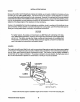
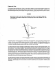
Propeller Shaft Coupling The propeller shaft coupling fitted to the transmission's output flange must transmit not only the power of the engine to turn the propeller shaft and propeller, but must also transmit the thrust of the engine/transmission either ahead or astern, The coupling bore should be carefully machined for a slight forced fit onto the shaft and an accurate mating surface for the coupling to the output flange of the transmission. The W 40NA engine is equipped with a Federal Flexible Coupling.
Take plenty of time in making this alignment and do not be satisfied wtth anything less than perfect results. The alignment is correct when the shaft can be easily slipped backward and forward into the counterbore, and when a feeler gauge indicates that the flanges come together at all points. The alignment between the propeller shaft coupling and the engine's coupling can contain an error no greater than one thousandth of an inch per Inch of the coupling diameter.
Exhaust System The exhaust system provides an outlet line to vent engine exhaust gases out of and away from the vessel. The system also discharges sea water which has passed through the engine's sea water circuit by mixing it with hot exhaust gases. This mixing helps cool the exhaust gases and exhaust elbow and plumbing.
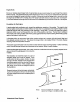
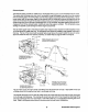
Exhaust Back-Pressure The exhaust discharge hose must be of adequate size and minimal run to prevent excessive exhaust back-pressure. Exhaust back-pressure should be checked before the engine is put into service. (Refer to the illustration.) Excessive backpressure will affect the engine's performance. To measure for back-pressure, use a mercury manometer, a pressure gauge, or a water column. A boatyard or marine mechanic should have a manometer or a pressure gauge.
Exhaust System Failures When the engine's sea water is fed into an exhaust system so that the full stream of this water strikes a surface, erosion takes place. This erosion may cause premature failures. The proper design of either a water jacketed or water injected 'wet" exhaust system to prevent this problem requires that the sea water inlet be positioned so that the entering stream of sea water does not directly strike a surface.
Connecting Pressure Sensing Devices to Oil Galleries Oil pressure sensing devices, such as senders and switches, must not be connected to an engine's oil gallery with the use of extended nipples or tees. The reason is simply that continued engine vibration causes fatigue of the fittings used to make such a connection. If these fittings fail, the engine loses its oil pressure and quickly seizes.
CAUTION DO NOT use a scoop-type through-hull fitting as a means of supplying sea water to the engine. Water pressure against this type of fitting, while the vessel is under sail, can push sea water past the sea water pump's impeller into the engine's exhaust system, filling it and the engine as well. Flush-type, clear, through-hull fittings are recommended and should be located on the hull so as to be below the waterline during all angles of boat operation.
Sea Water Intake System Make sure the intake system (sea water cooling system) is in proper order. Check that the through-hull inlet, sea cock and strainer are unobstructed. Sea cocks and strainers should be at least one size greater than the inlet thread of the sea water pump. The strainer should be of the type that may be withdrawn for cleaning while the vessel is at sea and should be mounted below the water line to ensure self-priming.
Electrical System The electrical system should be checked to ensure that all wiring harnesses are tied down properly with clamps or plastic ties, spaced at intervals close enough to prevent chafing from vibration. Check to ensure that all the engine's harness connections are tight and that they are connected to the appropriate terminals. !WARNINGI Do not smoke or allow an open flame near batteries. Lead acid batteries emit hydrogen, a highly-explosive gas.
PREPARATION FOR STARTING This section of the manual provides the operator with preparation, initial starting, break-in, starting (cold or warm), and stopping procedures. Follow the procedures as presented, for the conditions indicated, and your Westerbeke engine set will give you reliable performance and long service life. Fill the engine with 011 by pouring engine oil through the oil filler cap.
Starting System The W 40NA diesel engine uses an electric starter for both normal and cold weather starting. A cold start aid system is furnished on the W 40NA engine as standard equipment (part #36258). Both the thermostart device and the cold start aid are located on the air intake, manifold side of the engine. The PREHEAT button energizes the thermostart device assists in vaporizing the fuel at the intake manifold inlet.
STOPPING PROCEDURES In the cockpit of the boat, there Is a tee handle or a knob-type shut-of control. When this control is pulled OUTWARD, the control will STOP the engine. The other end of the shut-off control is attached to a lever on the top of the fuel Injection pump. (Pushing the shut-off control fully inward will place the engine in the RESTART - RUN position. When the engine is stopped, turn the Circuit Breaker located in the vessel to the OFF position.
As indicated above, operate the engine in moderation during the 50-hour break-in period. (On one hand don't baby the engine, but on the other hand, however, don't abuse it.) Starting Under Normal Conditions Follow the procedure below for normal starting of the engine: 1. Check the engine and transmission lubricant levels and fill, if necessary. 2. Make sure there is sufficient fuel on board. Keep fuel tank(s) as full as possible.
Starting Under Cold Conditions Under extremely cold temperatures, the following conditions can occur. Follow the instructions listed below when operating your engine in cold weather. LUBRICATING OIL TURNS VISCOUS - Make certain that the lubricating oil used conforms with the ratings for the prevailing atmospheric temperature. Refer to the "LUBRICATION SYSTEM" section of this manual, page 47 for an atmospheric/oil viscosity specification table.
FUEL SYSTEM Diesel Fuel Use No.2 diesel fuel with a cetane rating of 45 or higher. Never use kerosene or home heating oil since these fuels do not have the same lubricating properties as No.2 diesel fuel. In cold weather particular1y, water vapor is produced by condensation when air is present in the fuel tank. Keep fuel tank(s) full and completely free of dirt and water. Fuel Filters A primary fuel filter of the water entrapment type must be installed between the fuel tank and the engine.
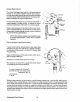
Priming and Bleeding the Fuel System The W 40NA engine has only one replaceable fuel filter located on the engine-mounted fuel system. This fuel filter is located just after the discharge side of the mechanical fuel lift pump Gust below the fuel filter). The manual-bleeding design of the fuel system allows the fuel filter to be easily serviced. To replace the fuel filter, remove and replace filter elements as described in the "Replacing Filter Elements", section of this manual, page 35.
NOTE: As a safety precaution, place a small plastic trash bag containing a few cloth rags around and under the secondary filterto catch any fuel that may spill from within the filter when it is removed. Also note that when working the manual priming lever on the fuel lift pump, move the lever up and down using long, even strokes. DO NOT operate the lever using rapid jerks. In some rare instances, the fuel lift pump may be at or near its internal maximum pump stroke.
4. Using the 5/16" box wrench or the 1/4" drive 5/16" socket wrench, open the #3 bleed screw and bleed this portion of the fuel Injection pump in the same manner as described in step #3. Proceed to step #5 NOTE: Make sure that the throttle Is fully open and the engine's shut-off lever is in its RUN pos~lon before proceeding to step #5. 5. Using a 5/8" open end wrench, loosen all four high pressure injector line nuts (#4), located at the base of each injector, one to two turns.
While the likelihood of having to service the fuel system at sea is small, the possibility does exist. Therefore, we recommend that a replacement fuel filter be carried on board at all times. Each fuel filter comes with two O-ring gaskets. Select the part numbers for this fuel filter from your Parts List and purchase spares from your local Westerbeke Dealer or Distributor.
Fuel Injection Pump The fuel injection pump is one of the most important components of the diesel engine and, therefore, calls for the utmost caution in handling. Furthermore, the fuel injection pump has been thoroughly bench-tested and should not be tampered with. Idle speed and timing adjustment are the only adjustments the servicing dealer can perform on the Injection pump. Other types of adjustments or repairs must be performed by a qualified injection service shop.
ELECTRICAL SYSTEM Engine 12-Volt DC Control Circuit The Westerbeke 40NA propulsion engine has a 12-Volt DC electrical control circuit, as shown on the wiring diagrams which follow on pages 40 and 41. Refer to these diagrams when troubleshooting or servicing electrical components on the engine. CAUTION To avoid damage to the battery charging circuit, never shut off the engine battery switch while the engine is running.
Alternator CAUTION When testing the alternator circuit (charging circuit), do not use a high-voltage tester such as a megger; damaged diodes could result. During high-speed operation of the engine, do not disconnect the positive terminal of the battery from the B terminal of the alternator, nor disconnect the negative terminal of the battery from the ground. Damage to the alternator's diodes will result. When cleaning the engine with a steam cleaner, be careful to keep steam away from the alternator.
The charging system consists of two alternators with external voltage regulators, an engine-mounted circuit breaker, a battery and connecting wires. Because of the use of IC's (integrated circuits), the electronic voltage regulator is very compact and is mounted on the rear bracket of the alternator. Charging Voltage Test If you suspect that the alternator is not producing enough voltage to charge the engine's battery, perform the following voltage test. *'14 L T, BLUE @]"'----'[§=2T o 0..
W 40NA DC Control Circuit Wiring Diagram #37248 page 1 of 2 WIPING DIAGP.AM @s .. "" .. +~ W~ . ."...... .".. y'b rt " "" ~~'b "~ (!; .- I' I' ~ w_"" " CD ~ .D~ lO· ... ~ I"''''~£" o~ >~,os Westerbeke Diesel Engines 40 ~UEL ,- .
W 40NA DC Control Circuit Wiring Diagram #37248 page 2 of 2 SCHEMATIC OIAGRA\I1 A @ ~-. ~ ~",. '§l.,,, .... 0 L - - ! -_ _-j ® 41 "401'1.0. .... IRING ~ODIFICATIO"S AND-PARTS SUPPLIED BY HANSEN MARINE: EI'IGINEERING INC.
COOLING SYSTEM Description Westerbeke marine diesel engines are designed and equipped for fresh water cooling. Heat produced in the engine by combustion and friction is transferred to fresh water which circulates throughout the engine. This circulating fresh water cools the engine block and ~s internal moving parts. The heat is transferred externally from the fresh water to sea water by means of a heat exchanger, similar in function to an automotive radiator.
Electrical System The electrical system should be checked to ensure that all wiring harnesses are tied down properly with clamps or plastic ties, spaced at intervals close enough to prevent chafing from vibration. Check to ensure that all the engine's harness connections are tight and that they are connected to the appropriate terminals. IWARNINGI Do not smoke or allow an open flame near batteries. Lead acid batteries emit hydrogen, a highly-explosive gas.
PREPARATION FOR STARTING This section of the manual provides the operator with preparation, initial starting, break-in, starting (cold or warm), and stopping procedures. Follow the procedures as presented, for the conditions indicated, and your Westerbeke engine set will give you reliable performance and long service life. Fill the engine with oil by pouring engine oil through the oil filler cap.
Starting System The W 40NA diesel engine uses an electric starter for both normal and cold weather starting. A cold start aid system is furnished on the W 40NA engine as standard equipment (part #36258). Both the thermostart device and the cold start aid are located on the air intake, manifold side of the engine. The PREHEAT button energizes the thermostart device assists in vaporizing the fuel at the intake manifold Inlet.
DESCRIPTION OF INSTRUMENT PANEL Westerbeke 40NA engines are supplied with instrument panels. Read the following instruction carefully before operating the engine. RPM Gauge Oil Pressure Gauge Water Temperature Gauge Ammeter . Vo~age Gauge General The manually-controlled panel is equipped with an RPM gauge with an ELAPSED TIME meter which measures the engine's running time in HOURS and in 1/10 hours.
4. Ammeter Gauge: An Ammeter gauge is provided by the Dealer and is located in the lower right hand corner of the instrument panel. (The Ammeter is not shown in the photograph on the preceding page.) NOTE: An alarm buzzer is supplied with every panel. The installer is responsible for electrically connecting the buzzer to the four-pin connection on the engine's electrical harness.
STARTING PROCEDURE 1. Place the transmission in the NEUTRAL position and advance the throttle to its full open position for a cold engine, and partially open for a warm engine. 2. Turn the Circuit Breaker to the ON position. Make sure the push/pull stop lever has been returned to the RUN position. 3. Depress and hold the PREHEAT switch. Preheat according to the following chart: Atmospheric Temperature Preheating Time + 41' F (+ 5' C) or higher Approx. 10 sec. Approx. 20 sec. Approx. 30 sec. 1 minute.
Once the engine starts. move the throttle into a fast idle position (1000 - 1200 rpm). Check your instrumentation for proper engine operation. Make sure that sea water discharges along with the exhaust discharge. NOTE: Some unstable running may occur in a cold engine. but this condition should smooth out as the operating temperature of 170 - 190' F (77 - 88' C) is reached. Transmission Shifting To shift the transmission, use the remote control shifting lever located in the cockptt.
STOPPING PROCEDURES In the cockpit of the boat, there is a tee handle or a knob-type shut-of control. When this control is pulled OUTWARD, the control will STOP the engine. The other end of the shut-off control is attached to a lever on the top of the fuel Injection pump. (Pushing the shut-off control fully inward will place the engine in the RESTART - RUN posttion. When the engine is stopped, turn the Circuit Breaker located in the vessel to the OFF position.
As indicated above, operate the engine in moderation during the 50-hour break-in period. (On one hand don't baby the engine, but on the other hand, however, don't abuse it.) Starting Under Normal Conditions Follow the procedure below for normal starting of the engine: 1. Check the engine and transmission lubricant levels and fill, if necessary. 2. Make sure there is sufficient fuel on board. Keep fuel tank(s) as full as possible.
Starting Under Cold Conditions Under extremely cold temperatures, the following conditions can occur. Follow the instructions listed below when operating your engine in cold weather. LUBRICATING OIL TURNS VISCOUS - Make certain that the lubricating oil used conforms with the ratings for the prevailing atmospheric temperature. Refer to the "LUBRICATION SYSTEM" section of this manual, page 47 for an atmospheric/oil viscosity specification table.
Fresh water is pumped through the engine by a belt-driven fresh water circulating pump, absorbing heat from the engine. The fresh water coolant circulates through the engine's block absorbing heat, then passes through the thermostat into the exhaust manifold, to the heat exchanger where it is cooled, and then is returned to the engine block through the suction side of the fresh water circulating pump.
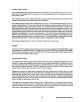
COO~ANT RECOVERY TANK ,.. P~IISS'URE CAP Coolant Recovery Tank, Recommended Installation Coolant from the engine, when heated during engine operation, will expand, lifting the spring-loaded mannold pressure cap, and enter the coolant recovery tank by way of the hose connecting the recovery tank to the exhaust mannold.
Thermostat Generally, thermostats are of two types. One is simply a choking device which opens and closes as the engine's temperature rises and falls. The second type has a bypass mechanism. Usually this is a disc on the bottom olthe thermostat which moves downward to close off an internal bypass passage within the head. Since 1980, each type of thermostat has a hole punched through it. The hole is a bypass to prevent the exhaust manifold from overheating during the engine's warm-up.
Alternator and Water Pump Drive 8elt Tension iWARNINGI Never attempt to adjust the drive belt's tension while the engine is in operation. CAUTION Excessive alternator and water pump drive belt tension can cause rapid wear of the belt and reduce the service life of the fresh water pump and alternator shaft bearings. Excessive slack or the presence of oil on the belt can cause belt slipping, resulting in high operating temperature, as well as insufficient alternator output.
LUBRICATION SYSTEM Engine Oil For engine lubrication, use lubricating oil designated for diesel service. These oils are classified according to the AFI specifications Into service grades CA, CB, CC and CD. The use of CC or higher (CD) grades, made by well-known manufacturers is recommended. The oil selected should be used thereafter. Engine Oil Viscosity (SAE Number) Use an oil having a viscosity best suited to the atmospheric temperature.
Engine Oil Change (to include filter) I\IIIIIIIIII! 111\ 1 ilill': \;:I;P:!' I' 1.1",. I, 1. Draining the Oil Sump Remove the oil drain hose from ~s attachment bracket and lower the end of the hose into a container to allow the oil to drain, or attach a pump to the drain hose and pump the oil out. Make sure the oil drain hose is properly secured in its holder after all of the old oil has been removed. . ," , 1' ~ , : : ! ~. Always observe the old oil as it is removed.
3. Filling the Oil Sump Add fresh oil through the oil filler cap on the valve cover (refer to the photographs on pages 5 and 6 for the location of the oil filler cap and lube oil dipstick). After refilling the oil, run the engine for a few moments while checking the engine's oil pressure. Ensure there is no leakage around the new oil filter or from the oil drain system, and then stop the engine. Then check the quantity of oil wtth the lube oil dipstick.
THE HBW 150 TRANSMISSION General The HBW 150 transmission Is equipped with a positively-driven. mechanically-operated helical gearing system. The servo-operated multlple-disc clutch requires only a minimum effort to change drives. This feature makes the transmission suitable for a single-lever remote control with a rod linkage. such as a Morse or Bowden cable. For safety reasons. the transmission is NOT filled with transmission fluid for shipment. Before leaving the factory. however.
NOTE: To check the transmission fluid level, remove the dipstick and wipe off all transmission fluid on the dipstick, and place the dipstick back in the hole where it was removed, making sure that the base of the dipstick's threaded portion rests on the transmission housing. Now remove the dipstick and see where the fluid measures on the dipstick. If the transmission's fluid level lies below the notch, add enough transmission fluid to raise the level back up to the notch. Do not overtill the transmission.
Controls The only controls required to operate the transmission is a single lever remote control cable using a 33C cable. The cable should be attached at right angles to the gear box lever using the cable bracket supplied with the unit. Both the gear box lever and the remote control lever must be in the NEUTRAL position when the cable is attached to the gear box lever.
Service If any seal on the transmission shows signs of leaking, have the transmission looked at by a qualified Hurth Servicing Dealer. This problem, especially concerning the rear seal, is often contributed to an improper alignment of the transmission's coupling and the propeller shaft's coupling. Refer to the "Alignment of the Engine" section of this manual, page 13. NOTE: A leaking rear seal can also be the result of a blocked vent hole in the head of the dipstick tube.
ENGINE TROUBLESHOOTING Introduction The tables which follow Indicate troubleshooting procedures based upon certain problem indicators, the probable causes of the problems, and the recommendations to overcome these problems. Note that the engine's control system (electrical system) is protected by a 20-Ampere manual reset circuit breaker located on the rear lifting bracket. problem probable Cause Verification/Remedy PREHEAT button is depressed: no panel indications.
Problem Probable Cause Verification/Remedy START switch Is depressed: no starter engagement. (continued) Loose battery connection. Check battery connections. Low battery voltage. Check voltage present at the solenoid S terminal when the START button is depressed. Shut-off lever. Return shut-off lever to the RUN position. Faulty fueling system. 1. Check for fuel to the engine. No ignition; engine cranks but does not start. 2. Check for air in the fuel system. Bleed the fuel system. 3.
Problem Probable Cause Verification/Remedy Engine stops. (continued) Transmission failure. Check the fluid level in the transmission. Transmission seizure will stop the engine. Engine will not turn over by engaging the starter. Battery is not charging. Alternator drive Check drive belt tension. Be sure the alternator turns freely. Check for loose connections. Check output with a voltmeter. Ensure that 12 Volts are present at the EXC connection. Check the alternator as described on page 39.
MAINTENANCE AND ADJUSTMENTS Introduction This section contains a scheduled preventive maintenance program and several adjustment procedures the owner/operator can periorm without the benefit of sophisticated and expensive tools and instruments. Preventive Maintenance Periorm the preventive maintenance in accordance with the schedules listed in the following paragraphs.
Servicing After Initial 50 Hours of Operation 1. Change the engine's lubrication oil and oil filter. 2. Replace the fuel filter element as described on page 35. Clean and replace the filter element and bowl of the primary fuel filter/Water separator, if one has been installed. *3. Torque the cylinder head nuts. *4. Adjust valve clearances. 5. Adjust the alternator, water pump and compressor drive belt tension, if required. 6.
6. Check the condition of all hoses and drive belts. Replace those that are badly worn. NOTE: Items highlighted by an asterisk (*) should be performed by a competent mechanic. Servicing After Every 800 Hours of Operation *1. Remove and check fuel injectors. Injector spray setting pressure: 2200 psi (155 kglcm 2) Minimum working pressure: POOR 2000 psi (140 kglcm 2) Eliminate undesirable injection conditions including after-dripping. Refer to the illustration to the right. *2.
VALVE CLEARANCE ADJUSTMENT CAUTION The cylinder head nuts must be retightened after the first 50-hours of break-in operation, and before adjusting the valves. Make sure the engine is cold when retightening the cylinder head nuts. Refer to the "TORQUE SPECIFICATION" section of this manual for proper tightening specifications, page 61. If the engine needs to be timed, refer to the ''TIMING ADJUSTMENT" section in the Technical Manual. Engine timing should be performed by a competent diesel mechanic.
TORQUE SPECIFICATIONS The following torque tensions apply when the components are lightly oiled before assembly. Lb-ft Kg-m N-m Cylinder Head Nuts 60 8.3 81 Connecting Rod Cap Bolts 42 5.8 57 • Main Bearing Cap Bolts 85 11.75 115 Flywheel Bolts 60 8.3 81 Idle Gear Hub Bolts 36 5.0 49 Crankshaft Pulley Bolt 150 20.7 203 Injector Securing Nuts 12 1.7 16 Fuel High Pressure Pipe Nuts 15 2.1 20 Alternator Pulley Nut 30 4.1 41 Thermostat Housing 10 1.
GENERAL TORQUE TIGHTENING CHART 1b-ft. UNLESS OTHERWISE INDICATED Grade 6T 6mm bolt/nut 8mm bolt/nut 10mm bolt/nut 12mm bolt/nut 14mm bolt/nut Grade 8T and 8.8 6mm bolt/nut 8mm bolt/nut 10mm bolt/nut 12mm bolt/nut 14mm bolt/nut - 0.7 1.0 1.6 2.3 3.2 4.7 5.6 8.2 7.7 -10.5 Westerbeke Diesel Engines - 1.5 - 1.8 - 2.8 - 3.2 -- 4.6 9 11 11- 13 1.2 1.5 2.5 2.9 3.7 4.1 6.1 6.9 9.4 10.
LAY-UP AND RECOMMISSIONING General Many owners rely on their boatyards to prepare their craft, including engines and generators, for lay-up during the off-season or for long periods of inactivity. Others prefer to accomplish lay-up preparation themselves. The procedures which follOW will allow you to perform your own lay-up and recommissioning, or to use as a check list ~ others do the procedures.
CAUTION Do not leave the engine's old lubricating oil in the sump over the lay-up period. Lubricating oil and combustion deposits combine to produce harmful chemicals which can reduce the life of your engine's internal parts. Fuel System Top off your fuel tanks with No.2 diesel fuel. Fuel additives should be added at this time to control algae and condition the fuel. Care should be taken that the additives used are compatible with the primary filter/water separator used in the system.
Cylinder Lubrication It is not necessary to remove the fuel injectors from the cylinder head to squirt light lubricating oil into the cylinders for the few months of normal lay-up. However, if you anticipate a longer lay-up period (12 months or.more), we recommended that this procedure be performed. The light oil in the cylinders will prevent the pistons rings from sticking to the cylinder walls. Make sure you have replacements for the injector and return line sealing washers.
4. Check the condition of the zinc anode in the sea water circuit and clean or replace the anode as needed. Note that it is not necessary to flush the antifreeze/fresh water solution from the sea water coolant system. When the engine is put into operation. the system will self-flush in a short period of time with no adverse affects. 5. Start the engine In accordance with procedures in the "PREPARATIONS FOR STARTING" section of this manual. page 22.
INDEX A ADJUSTMENTS, MAINTENANCE AND ..................................................................................................... 57 ADJUSTMENT, VALVE CLEARANCE ......................................................................................................... 60 Alignment (The HBW 150 Transmission) ................................................................................................... 51 Alignment of the Engine (Installation Checks) ..............................................
Controls (The HBW 150 Transmission) .......................................................................................................52 Connecting Pressure Sensing Devices to Oil Galleries (Installation Checks) ........................................... 18 Cooler, Oil, Assembly (Illustration) ..............................................................................................................49 Cooling System (Installation Checks) .............................................................
Fuel Injection Pump .................................................................................................................................... 36 Fuel System (Installation Checks) .............................................................................................................. 20 FUEL SYSTEM ............................................................................................................................................ 31 Fuel System (Lay-up and Recommissioning) ...........
a Oil Change. Engine (to Include filter) ..........................................................................................................48 Oil Cooler Assembly (illustration) ................................................................................................................49 all Drain Hose (Installation Checks) ...........................................................................................................17 Oil. Engine .....................................................
Shifting, Transmission ................................................................................................................................. 27 SOFTWARE DISCLAIMER, PRODUCT. ........................................................................................................ 1 Spares (Lay-up and Recommissioning) ..................................................................................................... 65 SPECIFICATION(S) GENERAL .....................................................
v VALVE CLEARANCE ADJUSTMENT ..........................................................................................................60 Ventilation (Installation Checks) ..................................................................................................................21 Viscosity, Engine Oil (SEA Number) ...........................................................................................................47 Voltage Test, Charging .......................................................
PARTS LIST Cylinder Block ................................................................ 100 Cylinder Head and Valves .............................................. 102 Crankshaft and Pistons .................................................. 104 Timing System and Camshaft ........................................ 106 Rocker Shaft and Cover ................................................. 108 Intake Manifold ............................................................... 110 Lube Oil Sump and Oil Pump ...
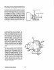
+---17 4--16 15 100 14
~ESTERBEKE REF 1 -1 1-2 2 4 5 6 7 8 9 10 11 12 13 14 15 16 17 18 19 20 21 22 23 24 25 26 27 28 29 30-1 30-2 31 32 33 34 35 36 37 38 40 41 42 40A - CYLINDER BLOCK PN NAME REMARKS 030870 011487 019990 012452 012458 012334 012356 031758 012475 031758 012661 011993 013341 012454 019992 012469 012623 012380 012456 031758 012473 012656 012406 012371 012464 012484 014686 012485 012363 012620 019994 012619 012666 020029 012652 031758 012473 031760 012498 020020 019965 013341 ENGINE ENGINE LINER PLUG PL
WESTERBEKE 40A - CYLINDER HEAD AND VALVES ~~ 24 21 ~20 --18 25 1 2 11 ~r-19 15 ---'ii!l 28 14 102
\.
~~~~~______ WESTERBEKE 40A - AND PISTONS CR ANKSHAFT 21 20 19 1 8 104
WESTERBEKE 40A - CRANKSHAFT AND PISTONS REF 1 2-1 2-2 2-3 2-4 3-1 3-2 3-3 3-4 4-1 4-2 5-1 5-2 6 7 8 9 10 1 1 -1 11-2 11-3 11-4 11-5 11-6 11 -7 12 13 14 15 16 17 18 19 20 21 PN NAME REMARKS 023105 012343 012414 012423 012519 012342 012349 012370 012373 014707 019969 012537 019968 014719 012383 012633 011857 012613 012595 023526 016356 012038 036428 012020 012039 031752 CRANKSHAFT BEARING BEARING BEARING BEARING BEARING BEARING BEARING BEARING WASHER WASHER WASHER WASHER GEAR SLINGER ADAPTER WASHER BOLT
~ESTERBEKE 40A - TIMING SYSTEM AND CAMSHAFT 3 l~ 1 8 ab, :!s---12 7 I 9 20 17 10 16 23 30 31 22 106
WESTERBEKE 40A - TIMING SYSTEM AND CAMSHAFT REF 1 2 3 4 5 6 7 8 9 10 11 12 13 14 15 16 17 18 19 20 21 22 23 24 25 26 27 28 29 30 31 PN NAME 012605 012460 012654 012440 012597 012625 031758 012474 012481 012541 012551 012689 014685 012388 012658 012652 031758 012474 012493 031760 012466 012678 031760 031758 012471 013536 031752 031754 012636 012500 012626 CAMSHAFT PUSHROD PLATE DOWEL GEAR PLATE LOCKWASHER CAPSCREW CAPSCREW TABWASHER PLATE GEAR BUSHING HUB GASKET STIFFENER LOCKWASHER CAPSCREW STUD NUT SEA
a <0 <0 ! 21 I ! <0 <2 ,I <0
WESTERBEKE 'lOA - ROCKER SHAFT AND COVER REF 1 2 3 4 5 6 7 8 9 10 11 12 13 14 15 16 17 18 19 20 21 22 23 24 25 26 27 28 29 PN NAME REMARKS 012681 012404 012429 012535 012467 012567 032184 012607 012606 012434 031759 012499 012494 012336 012335 012446 012362 012525 012539 012333 012488 012358 012462 012433 012372 012413 012419 012637 012331 COVER GASKET NUT WASHER SEAL CAP GASKET PUSHROD TAPPET NUT WASHER STUD STUD SHAFT SHAFT PLUG SNAPRING WASHER WASHER ROCKER SPRING BRACKET SCREW NUT CONNECTOR FERRULE
WESTERBEKE 40A - INTAKE MANIFOLD 12 1 10 11 0
WESTERBEKE 40A - INTAKE MANIFOLD REF 1 2 3 4 5-1 5-2 5-3 6-1 6-2 7 8-1 8-2 9-1 9-2 10 11 12 13 PN NAME REMARKS 012683 012556 011411 020021 022841 024881 013392 011 688 011615 031758 031582 031581 012688 019382 COVER FILTER CLAMP GASKET ADAPTER PLUG BUSHING START AID PLUG LOCKWASHER CAPSCREW CAPSCREW MANIFOLD MANIFOLD CAPSCREW ELBOW CLAMP HEATER AIR INTAKE AIR INTAKE HOSE 32 INTAKE MANIFOLD TO HEAD MANIFOLD TO 7/8UNF 7/8UNF-WHEN HEATER NOT INSTALLED 7/8UNF TO 1/8NPT ETHER TYPE 1/8NPT 031588 012639 01
~ESTERBEKE 27 40A - LUBE OIL SUMP AND OIL PUMP 26 19 a--- 18 17 1 112
WESTERBEKE 40A - LUBE OIL SUMP AND OIL PUMP REF 1 2 3 4 5 6 7 8 9 10 11 12 13 14 15 16 17 18 19 20 21 22 23 24 25 26 27 28 2':1 30 31 32 33 34 35 36 PN NAME REMARKS 035304 035305 035306 012473 031758 012652 012547 031758 012474 012407 012550 012659 012549 012548 012612 014816 012686 012491 012651 012473 031758 031759 020006 019950 012692 020017 SUMP PLUG WASHER CAPSCREW LOCKIJASHER STIFFENER STIFFENER LOCKIJASHER CAPSCREIJ GASKET STIFFENER GASKET SET STIFFENER STIFFENER DIPSTICK IJASHER STRAINE
3 9j/10 2 53~ 1 •" / 11 . .. ' ,-,,:" ........ ' 13~1O ",,' ,~~, ",S: .,.,.,.,,,.,,,.,.,It 55 ·<.-·._~~r l' ~--n ~Jy 15 ~', '." '~.' ~@ . -~. 5251----;;:~C': '--- ® J~::::.>~ 50 54 r /14 0 cr: E III (f) --i III ;u ~-\16 tD III :>< III 41 ::--B 40 .j>. ...o l> "~ - 34 :;> ~~ ~ "'~~ ~ 49 n a a r z on (f) -< (f) --i III 3: /20 n~.-=v/21 J. 28 ~~;;;;-""7:> 2:': .. '.--' .·t~Z " 26 \ .,,, "\ ...
WESTERBEKE 40A - COOLING SYSTEM REF 1 2 3 4 5 6 7 8 9 10 11 12 13 14 15 16 17 18 19 20 21 22 23 24 25 26 27 28-1 28-2 28-3 29-1 29-2 30 31 32-1 32-2 32-3 33 34 35 36 37 38 39 40 PN NAME REMARKS 015564 019334 024306 011653 019324 024907 021878 011652 031923 031764 031922 012009 012663 024688 011 951 013610 036379 012669 011143 016423 036366 032230 011386 030166 011885 011471 036896 013619 031786 031787 036838 036622 021878 024304 031506 031752 031753 021878 036325 036456 036324 022851 019321 022850 02
9:1r/ 10 .'tIl?} '\, / Jt11 12 '- ~10 13 "'\ t,f5p ~--~f,l '_C'i. I /14 15 £: m ~b ® UJ --i m ;0 !II m J< m J> o 41 '" n '" o o r 34 / ~ z '" UJ -< UJ --i m 3: ~df11)~ . . ----/, . ~1:'t:,;?:rX-; /20 45 1 26 -,"-',".
WESTERBEKE 40A - COOLING SYSTEM REF 41 42 43 44-1 44-2 44-3 45-1 45-2 46-1 46-2 47 413 49 50 51 52 53 54 55 56 57 PN NAME REMARKS 036260 0344134 0351131 031506 031752 031753 013334 013333 0316130 031770 0363132 0363131 0113972 024977 0247136 024704 024858 024637 024906 0316131 031770 KIT COOLER CLAMP CAPSCREU LOCKUASHER UASHER CONNECTOR FERRULE CAPSCREU LOCKUASHER LINE LINE ADAPTER KIT STRAP TANK CAP TUBING CLAMP CAPSCREU LOCKUASHER OIL COOLER EXCLUDING REF 15,33,34 & 36 LUBE OIL OIL COOLER MOUNT 1/4N
WESTERBEKE 40A - FRESH WATER PUMP AND WATER INJECTED EXHAUST ELBOW 118
WESTERBEKE 40A - FRESH WATER PUMP AND WATER INJECTED EXHAUST ELBOW REF 1 -1 1-2 2 3 4 5 5 7 8 9 10 11 12 13 14-1 14-2 15 PN 020035 019933 031758 031584 019987 031750 031583 035388 012673 012655 012674 036259 020439 034486 030183 035616 035747 NAME REMARKS PUMP FRESH WATER WATER PUMP REPAIR 1 1 5/15 4 2 KIT LOCKWASHER CAPSCREW PULLEY NUT CAPSCREW STUD GASKET PLATE GASKET KIT NIPPLE ELBOW ELBOW ELBOW PLUG QUAN 5/15NF X 2 FRESH WATER PUMP 5/16NF 5/16NF X 1-3/4 5/16NF X 2-1/8 WATER PUMP TO PLATE
\.IESTERBEKE 40A - SEA \.lATER PUMP , \ o \ ---N _---.
WESTERBEKE 40A - SEA WATER PUMP REF 1 2-1 2-2 2-3 3 4 5 G 7 8 9 10 11 12 13 PN NAME REMARKS QUAN 011143 016423 018169 018172 018160 018152 015153 018171 032183 018151 033104 018159 018170 018176 018148 GASKET PUMP HOUSING KIT SCREW CAM GASKET COVER LOCKWASHER SCREW KIT SEAL BEARING SHAFT KEY SEA WATER PUMP MOUNTING SEA WATER SEA WATER PUMP BODY PUMP MAJOR REPAIR BRASS-PUMP HOUSING TO CAM IMPELLER COVER IMPELLER BRASS-IMPELLER COVER IMPELLER AND COVER GASKET IMPELLER TO SHAFT 121 1 1 1 1 1 1 1 1 4
5 ::~ 'G::" 56 75~~.3= 45 ~. 60 \ .t1 ~~ 4 ~Q';~: "--~ 2~ '{f I '" ~ rn (J) -i 50"" rn ~ ~46 "- QP.7 ::0 m rn ;><: \ rn ' \ 53 76 • ~ _____ . - - 'Vk,II~ 43 / 9 ...
WESTERBEKE 'lOA - FUEL SYSTEM REF 1 2 3 4 5-1 5-2 6 7 8 9 10 11 12 13 14 15 16-1 16-2 17 18 19 20 21 22 23 24 25 26 27 28 29 30 31 32 33 34 35 36 37 38 39 40-1 40-2 41 42 43-1 43-2 44 45 PN NAME REMARKS 023909 031062 031061 016245 016443 035125 034857 032974 031756 019509 HOSE VALVE WASHER GASKET PUMP FUEL SUPPLY CHECK SEALING LIFT PUMP MOUNT FUEL LIFT FUEL LIFT PUMP REPAIR FUEL RETURN SEDIMENTER/WATER TRAP-OPTIONAL 5/16NC FUEL FUEL FILTER-SEE REF 12 FUEL FILTER-SEE REF 12 FUEL FILTER INCL REF 10-
75 45 ------------- 56 ~"{?.,\Iy- ... N / - . , ., ~ £: 111 (J) -f 111 " 60 \ .. ------' '" " III 111 '-:: \53 " ...<> 111 74 ~ 9 » " C 111 r (J) -< (J) -f 111 \..
WESTERBEKE 40A - FUEL SYSTEM REF 46 47 48 49 50 51 52 53 54 55 56-1 56-2 57 58 59 60 61 62-1 62-2 63-1 63-2 64 65 66-1 66-2 67-1 67-2 68 69 70 71 72 73 74 75 76-1 76-2 76-3 77 78 79 80 81 PN NAME REMARKS 012641 012645 012646 012647 035374 012653 035375 011945 012495 012501 019500 013343 013517 011 935 011943 019510 015197 011014 013755 023612 037394 011530 013345 031583 031758 013343 013344 013346 016676 019501 011 934 031765 031764 031630 013344 023920 LINE LINE LINE LINE INJECTOR FLANGE NOZZLE WASHER
4 18 17 f: PI '~, 50 I (J> 1 2 .... PI ::0 to PI " ... PI ~~ 22 ~ 0 » .~~II 23 25 ,)A /, \ "'- /I ;~ ~ ,,\~ 1'\,\/ \ \ ·1 -----'~U-<> I,'.. I \ \ \ \§J , 7 "~.::\~ J /j;i'~ ~~ to » n " PI Z C ru '" ')t< ~IK''C~>Y It);~;~·1 ) I !I I ~I. I _r ~\35 \'l7 \ ~_ , 39 .... ::0 » c ~A~ ~ Z I 41 n "4~ (J> ~44 :I ~ (J> (J> ~ 42 ----,(" ""/'\'") 27 ;.:ts III 1i1\-...6 I Jlbll "iYl<1I11 0 z :I 0 c ....z ~ z '" (J> -< (J> ....
WESTERBEKE 40A - BACK END - TRANSMISSION - MOUNTING SYSTEM REF 1 2 3 4 5 6 7 8 9 10 11 12 13-1 13-2 14-1 14-2 15-1 15-2 lEi-l 16-2 17 18 19-1 19-2 20-1 20-2 21 22-1 22-2 23-1 23-2 23-3 24 25 26 27-1 27-2 27-3 27-4 27-5 27-6 27-7 28-1 28-2 28-3 PN NAME REMARKS 034589 019262 031789 030593 034589 019262 011498 031764 031630 034833 019262 035332 034502 030230 034544 036648 030183 036614 017196 031786 031789 015887 020650 013629 031786 031790 024778 031267 030063 031248 024631 030049 024950 019262 031228
4 C £11 (f) -i 1 50 £11 ::0 ~~44 41 z (f) :3: ~ (f) (f) ~ 42 ';/'" ~ ~- a z :3: a c z -i ~ ..
~ESTERBEKE REF 29 30 31-1 31-2 31-3 31-4 31-5 31-6 31-7 32-1 32-2 32-3 33-1 33-2 34 35 36 37 38 39 40 41 42-1 42-2 43 44 45 46 47 48-1 48-2 49 50-1 50-2 51-1 51-2 PN 013629 031790 023706 023707 023708 023709 023710 023711 023712 031249 030048 031250 013629 034589 019262 019039 019398 031926 031789 034682 031928 034504 036341 036334 036338 034589 019262 031681 031770 013132 013133 013919 019059 011 779 011386 011405 40A - BACK END - TRANSMISSION - MOUNTING SYSTEM NAME REMARKS CAPSCRE~ Ml0 X 25 DIN 933
WESTERBEKE 40A - HBW TRANSMISSION SHIFTING BRACKET ~4 .
WESTERBEKE 40A - HBW TRANSMISSION SHIFTING BRACKET REF 1 2 3 4 5 6 7 8 9 10 11 12 13 PN NAME REMARKS QUAN 030756 030181 031786 013630 031847 031849 013870 013325 031873 033482 031752 031754 032161 NUT BRACKET LOCKWASHER CAPSCREW NUT LOCKWASHER SHIM CLAMP SCREW BALL JOINT LOCKWASHER NUT BRACKET PILLAR - M 8 SHIFT CABLE - TOP ENTRY M 8 DIN 127 M 8 X 25 DIN 933 10-32 10 CABLE CLAMP CABLE 10-32 X 5/8 1/4 1/4NF SHIFT CABLE - REAR ENTRY 131 2 1 2 2 2 2 1 1 2 1 1 1 1
WESTERBEKE 40A - STANDARD ALTERNATOR - OIL MANIFOLD 12 -4 ~- 7 20 21 132
WESTERBEKE 40A - STANDARD ALTERNATOR - OIL MANIFOLD REF 1 2 3 4-1 4-2 4-3 6 7 8 9 10 11 12 13 14 15 16 17 18 19 PN NAME REMARKS 031709 031776 024684 031555 031758 033381 011969 011615 036395 015122 CAPSCREW LOCKWASHER ALTERNATOR CAPSCREW LOCKWASHER WASHER MANIFOLD PLUG HOSE ELBOW ELBOW NIPPLE BRACKET STRAP PULLEY BELT BRACKET CLAMP SHIM CLAMP SENDER SW ITCH SWITCH CAPSCREW LOCKWASHER SPACER 1/2NC X 2 1/2 013328 011492 012060 035338 011548 035759 012955 013325 013870 013871 20 024132 21-1 21-2
WESTERBEKE 40A - ELECTRICAL HARNESS 6 7 134
WESTERBEKE 40A - ELECTRICAL HARNESS REF 1 3 4 5 6 7 8-1 8-2 9 10 11 12 PN NAME 024639 031678 031770 024683 035772 020005 036079 036602 030125 035109 032119 013355 SOLENOID CAPSCREW LOCKWASHER BREAKER BRACKET NUT HARNESS HARNESS SW ITCH SENDER BUSHING BUZZER REMARKS QUAN PREHEAT 1 2 2 1 1 2 1 1 1 1 2 1 7/16NF X 3/4 7/16 CIRCUIT 20 AMP CIRCUIT BREAKER AND SOLENOID PILLAR 8 PIN 12 PIN WATER TEMPERATURE-ALARM WATER TEMPERATURE REDUCER 1/2NPT TO 1/8NPT ALARM 135
WESTERBEKE 40A - INSTRUMENT PANEL 4 5 ~L 6~7 3 8 7 10 11 14 12 • I 0.
WESTERBEKE 40A - INSTRUMENT PANEL REF 1 2 3 4 5 6 7 8 9 10 11 12 13 14 15 16 17 18-1 18-2 19 20 PN NAME REMARKS 033866 030913 030119 035118 035114 035108 03511 0 033865 033693 030003 033684 030002 024996 030001 035111 033682 030148 033764 019031 011917 036630 PANEL SCREW COVER HOLDER LAMP METER METER PANEL SWITCH NUT COVER SPACER WINDOW SCREW VOLTMETER DECAL CABLE SIJITCH CAP METER DRAWING INSTRUMENT ASSEMBLY QUAN PANEL REAR LAMP-IJEDGE BASE INSTRUMENT-WEDGE BASE IJATER TEMPERATURE OIL PRESSUR
WESTERBEKE W40NA - ALTERNATORS AND COMPRESSOR MOUNTING SYSTEM \ i§Y ~ <0 '" '" 138 ....
WESTERBEKE W40NA - ALTERNATORS AND COMPRESSOR MOUNTING SYSTEM REF 1 2 3 4 5 6 7 8 9 10 11 12 13 14 15 16 17 18 19 20 21 22 23 24 25 26 27 28 29 30 31 32 33 34 35 36 37 38 39 40 41 42 PN NAME 031719 011548 036430 024684 036429 031776 031774 036427 031553 031758 033381 033064 031764 031633 031632 036452 033537 031765 031764 031762 036413 031553 CAPSCREW PULLEY SPACER ALTERNATOR SPACER LOCKWASHER NUT BRACKET CAPSCREW LOCKWASHER WASHER STRAP LOCKWASHER CAPSCREW CAPSCREW BRACKET CAPSCREw WASHER LOCKWASHER
~ESTERBEKE REF 3 4 5 6 7 8 9 10 11 12 13-1 13-2 13-3 13-4 13-5 13-6 14 40A - MISCELLANEOUS PN NAME REMARKS 019934 020719 020720 032974 013758 015010 020654 011988 020502 012169 034936 033340 033341 033342 036680 033943 033327 GASKET SET GASKET SET GASKET SET FILTER PAINT STRAINER SPLITTER KIT MANUAL LINE MUFFLER CONNECTOR CONNECTOR CONNECTOR ADAPTER KIT VALVE UPPER 1 LOIJER 1 COMPLETE 1 SEDIMENTER/IJATER TRAP 1 RED AEROSOL SPRAY CAN 1 SEA ~ATER 1 ALTERNATOR OUTPUT 1 FUEL HARDIJARE 1 TECHNICAL 1 FL