
Integration Manual

DT50RF (5127)
Integration Manual
Michael Aeschbacher
Doc.-Name: DT50RF_Integrator_Manual.docx, V1.3, Doc.-No.: 5127.30.316
Document date: 2020-05-06 – printed versions are uncontrolled copies!
© Neratec Solutions AG, CH-8608 Bubikon, Company Confidential
Page 5 (7)
2 Module installation instructions
2.1 General note
The module cannot be tested without a baseboard. Therefore, we have a limited modular approval. The module
shall be used always in combination with a Neratec DT50 baseboard.
2.2 Installation
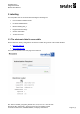
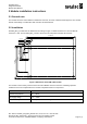
DT50RF_MK2_1 module has the dimensions according to Figure 1. Module thickness is 5 mm and with RF
connectors 7 mm. The DT50RF_MK2_1 need to be fixed to the end product with four M2.5 screws.
43.0mm
40.1mm
34.35mm
18.4mm
16.9mm
65.95mm
8.65mm
2.9mm
63.05mm
6.1mm
4.0mm
3.2mm
Figure 1 Dimensions of DT50RF_MK2 module
The module is connected by a PCIe interface and three MMCX antenna connectors. Following operation
conditions need to be complied when the module is implemented into an end product.
Parameter
Value
Operation temperature
-40 … +85°C
3.3V supply voltage
2.97 … 3.63V
Current consumption
2500mA peak; 2000mA average