6619-2202 TDW-33 DIN-rail Tele V.90 modem www.westermo.
Legal information The contents of this document are provided “as is”. Except as required by applicable law, no warranties of any kind, either express or implied, including, but not limited to, the implied warranties of merchantability and fitness for a particular purpose, are made in relation to the accuracy and reliability or contents of this document. Westermo reserves the right to revise this document or withdraw it at any time without prior notice.
Safety Before installation: This modem is for restricted access area use only. Read this manual completely and gather all information on the unit. Make sure that you understand it fully. Check that your application does not exceed the safe operating specifications for this unit. This unit should only be installed by qualified personnel. This unit should be built-in to an apparatus cabinet, or similar, where access is restricted to service personnel only.
Agency approvals and standards compliance Type Approval / Compliance EMC EN 61000-6-2, Immunity industrial environm EN 55024, Immunity IT equipment EN 61000-6-3, Emission residential environments FCC part 15 Class B EN 50121-4, Railway signalling and telecommunications apparatus IEC 62236-4, Railway signalling and telecommunications apparatus Safety EN 60950-1 and UL 60950-1, IT equipment PSTN CS 03 Part 1, issue 9 FCC part 68, TIA-968-A ETSI TS103 021-1, ETSI TS103 021-2, ETSI TS103 021-3 AS/ACIF S0
If trouble is experienced with this equipment TDW-33, for repair or warranty information, please contact Westermo Data Communication,Inc. 11200 Westheimer,Suit 900. Houston,TX,,77042. Phone number: 713-240-0367. If the equipment is causing harm to the telephone network, the telephone company may request that you disconnect the equipment until the problem is resolved. There are no repairs the customer/user can perform inside the modem.
Declaration of Conformity Westermo Teleindustri AB Declaration of conformity The manufacturer Westermo Teleindustri AB SE-640 40 Stora Sundby, Sweden Herewith declares that the product(s) Type of product Model DIN-rail Tele modem TDW-33 Art no 3619-0001 Installation manual 6619-2201 is in conformity with the following EC directive(s).
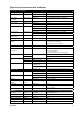
Type tests and environmental conditions Electromagnetic Compatibility Phenomena Test ESD EN 61000-4-2 Description Enclosure contact Enclosure air Enclosure Test levels ± 6 kV ± 8 kV 20 V/m 80% AM (1 kHz), 80 – 2000 MHz 20 V/m pulse modulated 200 Hz, 900 ± 5 MHz ± 2 kV ± 2 kV ± 2 kV line to earth, ± 2 kV line to line ± 2 kV line to earth, ± 1 kV line to line ± 2 kV line to earth, ± 2 kV line to line 10 V 80% AM (1 kHz), 0.15 – 80 MHz 10 V 80% AM (1 kHz), 0.15 – 80 MHz 100 A/m, 50 Hz, 16.
Description The TDW-33 is designed to function reliably within industrial environments and in areas of high level interference. The modem has an RS-232 interface supporting terminal data rates up to 115 kbit/s. The TDW-33 is a V.90 modem meaning that it can support data rates of up to 56 kbit/s on the PSTN line side. The modem is equipped with transient protection on the line side and a “watchdog” that monitors and automatically resets the modem in the event of a fault.
Interface specifications Power LV Rated voltage Operating voltage Rated current Rated frequency Inrush current I2t Startup current* Polarity Isolation to Connection Connector size Shielded cable 12 to 48 VDC or 12 to 34 VAC 10 to 60 VDC or 10 to 42 VAC 150 mA @ 12 VDC 70 mA @ 24 VDC 40 mA @ 48 VDC 150 mA @ 12 VAC 70 mA @ 24 VAC DC: – AC: 48 – 62 Hz 0.25 A2s 0.30 Apeak Polarity independent All other ports 3 kVrms 50 Hz 1 min Detachable screw terminal 0.2 – 2.
RS-232 (DCE) Position D-sub Direction* No. 1 No. 2 No. 3 No. 4 No. 5 No. 6 No. 7 No. 8 No. 9 Out Out In In – Out In Out Out Position Screw terminal* – No. 2 No. 1 No. 3 No. 5 No.
LED Indicators LED TD Transmit data RD Receive data RTS Request to send DCD Data carrier detect DTR Data terminal ready REL Reliable mode LINE PWR Power 6619-2202 Status OFF ON / FLASH OFF ON / FLASH OFF ON OFF ON OFF ON OFF ON FLASH OFF ON FLASH OFF ON FLASH Description No data The modem receiving data on the DTE interface No data The modem transmitting data on the DTE interface RTS signal is inactive RTS signal is active DCD signal is inactive DCD signal is active, modem has detected a car
Mounting This unit should be mounted on 35 mm DIN-rail, which is horizontally mounted inside an apparatus cabinet, or similar. Snap on mounting, see figure. CLICK! CLICK! Cooling This unit uses convection cooling. To avoid obstructing the airflow around the unit, use the following spacing rules. Minimum spacing 25 mm (1.0 inch) above /below and 10 mm (0.4 inches) left /right the unit. Spacing is recommended for the use of unit in full operating temperature range and service life. 10 mm * (0.
Windows configuration tool TD-Tool The TD-Tool is a PC – application program with a graphical interface for easy configuration of the complex functions found on the encolsed CD or at the Westermo website. Please refer to TD-Tool for a complete description of the functionality of the Windows program.
Application examples … TDW-33 connected to TDW-33 with DTR signal call PSTN Network Configure the units AT&F AT&W Set the unit to factory default Store default settings Set up the connection – The dialling modem AT&Z0=nnn AT&S0 AT&B1 AT&W Switch DTR from OFF to ON Store the number of the remote modem in the dialling TDW-33 Set DSR signal always high (if this signal is used to trig the DTR) Activates automatic DTR dialling if DTR switches from low (OFF) to high (ON) Save settings The modem will now dia
… Frequently used settings for PLC-systems PSTN Network Most PLC-systems and other industrial applications where modems are used require the same changes to the standard settings. The most commonly encountered problems concern speed, parity and control signals from the connected equipment. If this action does not solve the problem the modem’s answering codes and possible echoing of commands might be the source of the difficulty. Below follows a list of commands that might resolve the problems.
… TDW-33 – Secure Call-back The TDW-33 is connected to a PLC which one want to restrict access to. The TDW-33 can support access control through the Secure Callback function. In this example password and callback to a predefined number is chosen. The modem in the calling end is here chosen to be a PSTN modem, but can be any of the PSTN, ISDN or GSM modem from the Westermo product range.
Configure the TD-36 AT&F AT+IPR=9600 AT+ICF=3,4 ATS0=1 AT&W Set the unit to factory default DTE baudrate 9600 Character framing 8 data, 1 stop, parity none Auto answer after first ring Store default settings Set up the connection The dialling modem TD-36 ATD0705123456 NO CARRIER The answering modem TDW-33 TDW-33 answers the call and requests to TDW-33 TDW-33 verifies the password to the passwords stored and if true compare dissconnects.
… TDW-33 – Silent answering on predefined number The TDW-33 is connected to a power meter which is remotely monitored. The TDW-33 shares the PSTN line with normal telephones which is preferred not to give a ring signal when the meter is read. The TDW-33 is configured to answer calls on the Caller ID received, the valid numbers to answer is programmed into the TDW-33. There exists a number of standards for sending Caller ID check which standard is used by your operator.
Westermo Teleindustri AB • SE-640 40 Stora Sundby, Sweden Phone +46 16 42 80 00 Fax +46 16 42 80 01 E-mail: info@westermo.se Westermo Web site: www.westermo.com Westermo OnTime AS Gladsvei 20 0489 Oslo, Norway Phone +47 22 09 03 03 • Fax +47 22 09 03 10 E-mail: contact@ontimenet.com Westermo Data Communications Ltd Talisman Business Centre • Duncan Road Park Gate, Southampton • SO31 7GA Phone: +44(0)1489 580‑585 • Fax.:+44(0)1489 580586 E-Mail: sales@westermo.co.