
User guide

11
6643-2250
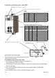
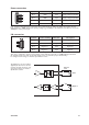
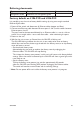
Power connection
I/O connection
1
2
3
4
4-position Product marking Direction Description
No. 1 +DC1 Input Supply voltage input DC1
No. 2 +DC2 Input Supply voltage input DC2
No. 3 -COM Input Common
No. 4 -COM Input Common
Lynx supports redundant power connection. The positive inputs are +DC1 and +DC2, the negative input for
both supplies are –COM. Connect the primary voltage (e.g. +24 VDC) to the +DC1 pin and return to one of the
–COM pins on the power input.
1
2
3
4
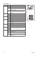
4-position Product marking Direction Description
No. 1 Status + Output Alarm relay (status) contact
No. 2 Status – Output Alarm relay (status) contact
No. 3 Digital in + Input Digital in +
No. 4 Digital in – Input Digital in –
The Status output is a potential free, opto-isolated normally closed solid-state relay.
This can be configured to monitor various alarm events within the Lynx unit, see WeOS Management Guide.
An external load in series with an external voltage source is required for proper functionality.
For voltage/current ratings, see Interface Specification section.
The Digital in is an opto-isolated
digital input which can be used to
monitor external events. For volt-
age/current ratings, see Interface
Specification section:
Lynx
External
Load
Status
V
V
Digital In
+
1
2
3
4
–