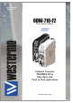
6651-2211 ODW-710-F2 Fibre Optic Modem Industrial Converter PROFIBUS DP to Fibre Optic Link. Point to Point applications www.westermo.
Legal information The contents of this document are provided “as is”. Except as required by applicable law, no warranties of any kind, either express or implied, including, but not limited to, the implied warranties of merchantability and fitness for a particular purpose, are made in relation to the accuracy and reliability or contents of this document. Westermo reserves the right to revise this document or withdraw it at any time without prior notice.
Safety ! Before installation: Read this manual completely and gather all information on the unit. Make sure that you understand it fully. Check that your application does not exceed the safe operating specifications for this unit. This unit should only be installed by qualified personnel. This unit should be built-in to an apparatus cabinet, or similar, where access is restricted to service personnel only.
Note. Fibre Optic Handling Fibre optic equipment requires careful handling as the fibre components are very sensitive to dust and dirt. If the fibre is disconnected from the modem, the protective plug on the transmitter/receiver must be replaced. The protective plug must be kept on during transportation. The fibre optic cable must also be protected in the same way. If this recommendation is not followed, it can jeopardise the warranty.
ATEX Information (Applicable for ODW-710-F2 EX only) General This unit is intended for use in Zone 2 hazardous location only. Marking II 3 G Ex nA IIC T4 Gc SPECIAL CONDITION WARNING – DO NOT SEPARATE WHEN ENERGIZED Indicate that this unit complies with relevant European standards that are harmonised with the 94/9/EC Directive (ATEX). II 3 G Ex nA IIC T4 Gc SPECIAL CONDITION 6651-2211 Equipment group II.
Ratings Power Ambient temperature Ingress protection (IP) Maximum surface temperatur (12 – 48) VDC; 400 mA –40ºC ≤ Ta ≤ +60ºC IP21 135ºC (temperature class T4) Safety Control Drawing Degree of protection Ambient temperature Installation spacing IP 21 –40°C to +60°C Minimum 25 mm above / below Minimum 10 mm left / right Direction relative this unit! Position 1 2 3 Descripton In & out / Relay contact (NO) In & out / Relay contact (C) In & out / Relay contact (NC) Input / Output values Uin = 60 VDC max I
SPECIAL CONDITION FOR SAFE USE Ambient temperature: This unit is designed for use in extreme ambient temperature conditions as follows: –40 ºC ≤ Ta ≤ +60 ºC Installation in an apparatus cabinet: This unit requires installation in an Ex certified apparatus cabinet suitable for the area of use and providing a degree of protection of at least IP54. Resistance to impact: This unit requires installation in an apparatus cabinet where adequate resistance to impact is provided by the apparatus cabinet.
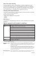
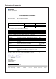
Declaration of Conformity Westermo Teleindustri AB Declaration of conformity The manufacturer Westermo Teleindustri AB SE-640 40 Stora Sundby, Sweden Herewith declares that the product(s) Type of product Model Art no Industrial fiberoptic repeaters/media converters ODW-700 series 3651-07xx ODW-700EX series 3651-37xx is in conformity with the following EC directive(s).
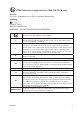
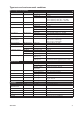
Type tests and environmental conditions Electromagnetic Compatibility Phenomena Test ESD EN 61000-4-2 RF field AM modulated IEC 61000-4-3 RF field 900 MHz Fast transient ENV 50204 EN 61000-4-4 Surge EN 61000-4-5 RF conducted EN 61000-4-6 Pulse Magnetic field Voltage dips and interruption EN 61000-4-9 EN 61000-4-11 Mains freq. 50 Hz Mains freq.
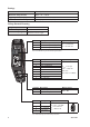
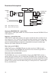
Functional description Switches LED’s POWER +VA +VB COM O V P Internal Electronics O V P NO C NC SFP Fibre transceiver SFP Fibre transceiver OVP OCP PROFIBUS DP RxD/TxD-P RxD/TxD-N SHIELD COM STATUS O C P CH 1 TX RX CH 2 TX RX Over Voltage Protection Over Current Protection Converter PROFIBUS DP – optical fibre ODW-710-F2 is a fibre optic modem that converts between electrical PROFIBUS DP and a fibre optical link.
Interface specifications Power Rated voltage Operating voltage Rated current Rated frequency Inrush current I2t Startup current* Polarity Redundant power input Isolation to Connection Connector size Shielded cable ODW-710-F2: 12 to 48 VDC and 24 VAC ODW-710-F2 Ex: 12 to 48 VDC ODW-710-F2: 10 to 60 VDC and 20 to 30 VAC ODW-710-F2 Ex: 10 to 60 VDC 400 mA @ 12 VDC 200 mA @ 24 VDC 100 mA @ 48 VDC ODW-710-F2: DC and 48 to 62 Hz ODW-710-F2 Ex: DC 0.2 A2s 1.
PROFIBUS DP (RS-485) Electrical specification Data rate Data format Protocol Data Rate detection Retiming Turn around time Transmission range Settings Protection Isolation to Connection Shielded cable Conductive housing EIA RS-485 / EN 50 170 9 600 bit/s, 19.2, 93.75, 187.5, 500 kbit/s, 1.
FX (Fibre) Fibre connector Fibre type Wavelength nm, connector 1 Wavelength nm, connector 2 Transmitter Output optical power min/max Receiver Input sensitivity, max Receiver Input optical power, max Optical power budget, worst-case Bit error rate (BER) Transceiver type Laser class 6651-2211 Bi-Di LC-40 LC Simplex Singlemode 9/125 μm Tx 1310, Rx 1550 Tx 1550, Rx 1310 –8/0 dBm Bi-Di LC-20 LC Simplex Singlemode 9/125 μm Tx1310, Rx 1550 Tx 1550, Rx 1310 –14/8 dBm –34 dBm –32 dBm –3 dBm 0 dBm 26 dB 18 d
Location of Interface ports, LED’s and DIP-switches ODW-710-F2 LED Indicators(for details see page 15) DIP-switches accessible under lid (for details see page 16–17) Status screw terminal Position 1 2 3 Description Contact with C when fibre optical links are in operation Common Open (no contact with C) when fibre optical links are not in operation Product marking NO C NC PROFIBUS DP (RS-485) D-sub Position FX(Fibre) (for details see page 12–13) Direction* Description 1 – – 2 – – 3 In/Out Rx
LED Indicators LED PWR Power Status ON Flashing BA OFF ON Bus active CH 2 OFF ON Channel 2 link status Flashing OFF CH 1 ON Channel 1 link status Flashing OFF DPR Flash Receive PROFIBUS DP OFF FR Flash Receive fibre link OFF FL R ON Failure link remote Flashing FL L ON Failure link local Flashing 6651-2211 Description Power is on. Unit configured as focal point (DIP-switch S2:3 is ON). Power is off.
DIP-switch settings ! Before setting DIP-switches: Prevent damage to internal electronics from electrostatic discharges (ESD) by discharging your body to a grounding point (e.g. use of wrist strap). S1 S2 S2 DIP-switch ON 1 2 3 4 5 6 7 8 ON 1 2 3 4 5 6 7 8 ON 1 2 3 4 5 6 7 8 ON 1 2 3 4 5 6 7 8 16 Multidrop mid unit or redundant ring member. Multidrop end unit. E.g. the first or last unit in a multidrop network. Redundant ring master unit. Only one master unit allowed in a ring.
S1 DIP-switch S2 DIP-switch ON ON 1 2 3 4 5 6 7 8 1 2 3 4 5 6 7 8 ON ON 1 2 3 4 5 6 7 8 1 2 3 4 5 6 7 8 ON ON 1 2 3 4 5 6 7 8 1 2 3 4 5 6 7 8 ON ON 1 2 3 4 5 6 7 8 1 2 3 4 5 6 7 8 ON ON 1 2 3 4 5 6 7 8 1 2 3 4 5 6 7 8 ON ON 1 2 3 4 5 6 7 8 1 2 3 4 5 6 7 8 ON ON 1 2 3 4 5 6 7 8 1 2 3 4 5 6 7 8 ON ON 1 2 3 4 5 6 7 8 1 2 3 4 5 6 7 8 ON ON 1 2 3 4 5 6 7 8 1 2 3 4 5 6 7 8 ON ON 1 2 3 4 5 6 7 8 1 2 3 4 5 6 7 8 ON ON 1 2 3 4 5 6 7 8 1 2 3 4 5 6 7 8 ON ON 1 2 3 4 5 6
Multidrop configuration RX2 TX2 TX1 RX2 TX1 RX2 TX1 RX2 RX1 TX2 RX1 TX2 RX1 TX2 End Unit S2: 2 ON PROFIBUS Master (PLC) TX1 RX1 End Unit S2: 2 ON PROFIBUS Slave PROFIBUS Slave PROFIBUS Slave Prepare the PROFIBUS units … Configure PROFIBUS network, with master and slaves. Check that the application is running correctly with the electrical PROFIBUS network. Note: In an ODW-710-F2 fibre optic network there will be some additional processing delays that do not exist in an electrical bus.
Behavior during optical link failure RX2 TX2 TX1 RX2 TX1 RX1 TX2 RX1 RX2 TX1 RX2 TX2 RX1 TX2 Faulty segment End Unit S2: 2 ON FL R LED is on PROFIBUS Master CH 1 LED is off PROFIBUS Slave FL L LED is on TX1 RX1 End Unit S2: 2 ON CH 2 LED is off PROFIBUS Slave FL L LED is on FL R LED is on PROFIBUS Slave If an optical fibre segment fails, all communication with units beyond the faulty fibre segment will be lost.
Redundant ring configuration Fibre pair used to carry data. Redundant fibre pair. Not used under normal operation. RX2 TX1 RX2 TX1 RX2 TX1 RX2 TX1 TX2 RX1 TX2 RX1 TX2 RX1 TX2 RX1 Focal Point S2: 3 ON Ring Member Ring Member Ring Member PROFIBUS Slave PROFIBUS Slave PROFIBUS Slave PWR LED Flashing to indicate master PROFIBUS Master Prepare the PROFIBUS units … Configure PROFIBUS network, with master and slaves.
Data from the PROFIBUS master is received at the ODW-710-F2 electrical port (as indicated by the DPR LED). The data rate is automatically detected (as indicated by the BA LED) and data bits are retimed according to the determined rate and sent out on the optical fibre at CH 1. The first ODW-710-F2 ring member receives data at optical fibre CH 2 (as indicated by the FR LED). The data rate is automatically detected (as indicated by the BA LED) and data is sent out on the electrical port.
Calculating system processing delay Data exchange between a PROFIBUS DP master and slave via ODW-710-F2 fibre optic link will be delayed due to the length of the optical fibre and the signal processing within the ODW-710-F2. The signal processing delay is dependent on the data rate, and the fibre delay is dependent on the total length of the optical fibre. The additional time resulting from the optical fibre and ODW-710-F2 is the Overall system delay. Delay @ < 1.
Reconfiguration time under faulty condition The reconfiguration time is determined by the time it takes to detect a faulty fibre segment plus the time it takes to transport an error status message through to the ODW710-F2 focal point unit. The time to transport an error status message to the focal point unit is dependent on how many units the error status message has to be repeated through and the total fibre length delay.
About the interfaces Power The power terminal has two independent inputs, +VA and +VB, allowing redundant power input. The ODW-710-F2 power supply is galvanically isolated from all other interfaces. Optical fibre interfaces ODW-710-F2 uses Small Form Factor Pluggable (SFP) transceivers. This means that a wide range of different fibre transceivers and connectors can be used (see page 12–13). PROFIBUS DP interface The PROFIBUS DP interface is a female 9-position D-sub.
About the automatic data rate detection ODW-710-F2 automatically detects the data rate by monitoring incoming PROFIBUS data frames on both the electrical and optical interfaces. When the data rate has been established the BA LED will go active. If no data frames are transmitted for a period of time the automatic data rate detection will restart and the BA LED will go inactive. The idle time before the automatic data rate detection restarts is set using DIP-switches S2:4 and S2:5.
Mounting This unit should be mounted on 35 mm DIN-rail, which is horizontally mounted inside an apparatus cabinet, or similar. Snap on mounting, see figure. CLICK! CLICK! Cooling This unit uses convection cooling. To avoid obstructing the airflow around the unit, use the following spacing rules. Minimum spacing 25 mm (1.0 inch) above /below and 10 mm (0.4 inches) left /right the unit. Spacing is recommended for the use of unit in full operating temperature range and service life. 10 mm * (0.
Westermo • SE-640 40 Stora Sundby, Sweden Tel +46 16 42 80 00 Fax +46 16 42 80 01 E-mail: info@westermo.com www.westermo.com Sales Units Westermo Data Communications China sales.cn@westermo.com www.cn.westermo.com France infos@westermo.fr www.westermo.fr Germany info@westermo.de www.westermo.de North America info@westermo.com www.westermo.com Singapore sales@westermo.com.sg www.westermo.com Sweden info.sverige@westermo.se www.westermo.se United Kingdom sales@westermo.co.uk www.westermo.co.