
User guide


14
6651-2211
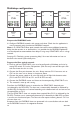
Location of Interface ports, LED’s and DIP-switches
ODW-710-F2
Position Direction* Description Product
marking
1 In Common voltage COM
2 In Voltage A +VA
3 In Voltage B +VB
4 In Common voltage COM
Power
screw terminal
LED Indicators(for details see page 15)
Position Description Product
marking
1 Contact with C when fibre optical
links are in operation
NO
2 Common C
3 Open (no contact with C)
when fibre optical links are
not in operation
NC
Status
screw terminal
Position Direction* Description
1 – –
2 – –
3 In/Out RxD/TxD-P
4 Out CNTR-P
5 – DGND
6 Out VP
7 – –
8 In/Out RxD/TxD-N
9 – –
* Direction relative this unit
FX(Fibre)
(for details
see page 12–13)
DIP-switches accessible under lid
(for details see page 16–17)
PROFIBUS DP (RS-485)
D-sub