
User guide


21
6651-2211
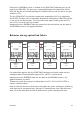
Data from the PROFIBUS master is received at the ODW-710-F2 electrical port (as indi-
cated by the DPR LED). The data rate is automatically detected (as indicated by the BA
LED) and data bits are retimed according to the determined rate and sent out on the opti-
cal fibre at CH 1.
The first ODW-710-F2 ring member receives data at optical fibre CH 2 (as indicated by
the FR LED). The data rate is automatically detected (as indicated by the BA LED) and data
is sent out on the electrical port. The ring member also repeats incoming data on CH 2
out on CH 1 on to the next ring member.
Responses from the PROFIBUS slaves are processed in the same fashion and sent back to
the PROFIBUS master in the opposite direction.
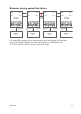
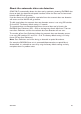
If an optical fibre segment fails, the ODW-710-F2 focal point will switch mode and start
sending out data on both optical fibre ports, CH 1 and CH 2, simultaneously.
Responses from the PROFIBUS slaves are sent back to the PROFIBUS master in the
opposite direction, as normal.
To determine witch fibre segment has failed, look at the FL L, CH 1 and CH 2 LED’s as
show in the picture above.
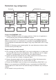
Note: If a fibre link fails there will be some time before the system reconfigures itself during
witch data may be corrupted or lost. See page 23 “Reconfiguration time under faulty con-
dition” for more information on how to determine the system reconfiguration time.
Behavior during optical link failure
RX2
TX2
Focal Point
S2: 3 ON
Ring Member Ring Member
FL R LED
is on
PWR LED
Flashing to
idicate master
FL L LED
is on
CH 1 LED
is off
Faulty
segment
PROFIBUS
Master
(PLC)
TX1
RX1
RX2
TX2
Ring Member
TX1
RX1
RX2
TX2
TX1
RX1
RX2
TX2
TX1
RX1
PROFIBUS
Slave
PROFIBUS
Slave
PROFIBUS
Slave
FL R LED
is on
FL L LED
is on
CH 2 LED
is off