6193-3201 RM-90 Wireless Ethernet Radio Modem www.westermo.
Thank you for your selection of the RM-90 Wireless Ethernet Modem. We trust it will give you many years of valuable service.
ATTENTION! Incorrect termination of supply wires may cause internal damage and will void warranty. To ensure your RM-90 enjoys a long life, double check ALL your connections with the users manual before turning the power on. Caution! For continued protection against risk of fire, replace the internal module fuse only with the same type and rating. CAUTION: To comply with FCC RF Exposure requirements in section 1.
FCC Notice: This user’s manual is for the WESTERMO RM-90 radio telemetry module. This device complies with Part 15.247 of the FCC Rules. Operation is subject to the following two conditions: … This device may not cause harmful interference and … This device must accept any interference received, including interference that may cause undesired operation. This device must be operated as supplied by WESTERMO Technologies.
Important Notice WESTERMO products are designed to be used in industrial environments, by experienced industrial engineering personnel with adequate knowledge of safety design considerations. WESTERMO radio products are used on unprotected license-free radio bands with radio noise and interference. The products are designed to operate in the presence of noise and interference, however in an extreme case, radio noise and interference could cause product operation delays or operation failure.
Chapter One INTRODUCTION The RM-90 Wireless Ethernet module provides wireless connections between Ethernet devices or Ethernet wired networks (LAN’s). It has an internal 900MHz spread spectrum frequency hopping wireless transceiver, which can be used without a radio license in many countries. The RM-90 has a standard RJ45 Ethernet connection which will operate at up to 100Mbit/sec. The module will transmit the Ethernet messages on the wireless band at up to 200 Kbit/sec. 1.
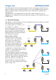
An Access Point could be used as a “Repeater” unit to connect two RM-90 Clients which do not have direct reliable radio paths. 6XXZhh Ed^ci 8a^Zci 8a^Zci A6C :i]ZgcZi 9Zk^XZ &.'#&+-#%#() &.'#&+-#%#,' Bridge vs Router Each RM-90 is configured 8a^Zci 6XXZhh Ed^ci 7g^Y\Z with an IP address for the 7g^Y\Z Ethernet side, and &.'#&+-#%#() &.'#&+-#%#,' another for the wireless A6C side. A Bridge connects devices within the same Ethernet network – for example, extending an existing Ethernet LAN.
There is limit of two Routers within the same radio network. There is no limit to the number of Bridges in the same network – although there is a limit of 255 Client units linked to any one Access Point. &.'#&+-#%#,' 8a^Zci 7g^Y\Z &.'#&+-#%#,' &.'#&+-#%#,( &.'#&+-#%#() 8a^Zci GdjiZg A6C 6 &.'#&+-#%#() &+.#'*)#&%'#&, 6XXZhh Ed^ci 7g^Y\Z A6C 8 &.'#&+-#%#,) 8a^Zci GdjiZg &+.#'*)#&%.#)% A6C 7 1.2 Getting Started Quickly Most applications for the RM-90 require little configuration.
Chapter Two INSTALLATION 2.1 General The RM-90 module is suitable for DIN-rail mounting. Terminals will accept wires up to 12 gauge (2.5 sqmm) in size. All connections to the module must be SELV. Normal 110-240V mains supply should not be connected to any terminal of the RM-90 module. Refer to Section 2.3 Power Supply. Before installing a new system, it is preferable to bench test the complete system. Configuration problems are easier to recognize when the system units are adjacent.
In certain circumstances, much longer distances can be achieved by reducing the transmitter power and using higher gain antennas. Although the effective radiated power at the transmitter end is the same, the additional antenna gain at the receiver gives increased distance. This is only true for locations of low background noise as the antenna gain will also increase the noise level. For example, in America where 4W ERP power is permitted, a combination of 0.
Where antennas are mounted on elevated masts, the masts should be effectively earthed to avoid lightning surges. For high lightning risk areas, surge suppression devices between the module and the antenna are recommended. If the antenna is not already shielded from lightning strike by an adjacent earthed structure, a lightning rod may be installed above the antenna to provide shielding. 2.2.1 Dipole and Collinear antennas.
2.2.2 Yagi antennas. A Yagi antenna provides high gain in the forward direction, but lower gain in other directions. This may be used to compensate for coaxial cable loss for installations with marginal radio path. The Yagi gain also acts on the receiver, so adding Yagi antennas at both ends of a link provides a double improvement. Yagi antennas are directional. That is, they have positive gain to the front of the antenna, but negative gain in other directions.
2.3 Power Supply The RM-90 module can be powered from a 10 – 30VDC power supply. The power supply should be rated at 1 Amp and be CSA Certified Class 2. The negative side of the supply should be connected to a good “ground” point for surge protection. The supply negative is connected to the unit case internally. The positive side of the supply must not 7 GH")-* be connected to earth. The DC supply may 6 be a floating supply or negatively grounded.
DB9 Connector Pinouts Pin Name Direction Function 1 DCD Out Data carrier detect – 2 RD Out Transmit Data – Serial Data Output 3 TD In Receive Data – Serial Data Input 4 DTR In Data Terminal Ready – 5 SG 6 DSR Out Data Set Ready – always high when unit is powered on. 7 RTS In Request to Send – 8 CTS Out Clear to send – 9 RI Signal Ground Ring indicator – 2.4.
=DHI GB".
2.5 Discrete (Digital) Input/Output The RM-90 has one on-board discrete/digital I/O channel. This channel can act as either a discrete input or discrete output. It can be monitored, or set remotely, or alternatively used to output a communications alarm status. If used as an “input”, the I/O channel is suitable for voltage free contacts (such as mechanical switches) or NPN transistor devices (such as electronic proximity switches). PNP transistor devices are not suitable.
Chapter Three OPERATION 3.1 Start-up “Access Point” Start-up An Access Point unit starts and immediately begins transmitting periodic messages called beacons. These beacon messages are messages contain information for Clients on how to establish a link with the Access Point. Any Client that hears the messages, which are not already linked to another Access Point unit, will respond and links will be established between the new Access Point and these Clients.
How a Link connection is lost The RM-90 will reset the Link if: … Excessive retries: When a RM-90 unit transmit a wireless message to another unit, the destination unit will transmit back an acknowledgment. If the source unit does not receive an acknowledgment, it will re-send the message – this is known as a “re-try”. Both Access Point and Client will drop the link if the number of retries for a single packet exceeds (7) times.
3.2 Default Configuration The default factory configuration of the RM-90 is … Bridge/Client … IP address192.168.0.1XX, where XX is the last two digits of the serial number (the default IP address is shown on the printed label on the back of the module) … netmask 255.255.255.0 … Username is “user” and the default password is “user” The RM-90 will temporarily load some factory-default settings if powered up with the Factory Default switch (on the end-plate of the module) in SETUP position.
… On the General tab enter IP address 192.168.0.1, Subnet mask 255.255.255.0, and default gateway 192.168.0.1. … Open Internet Explorer and ensure that settings will allow you to connect to the IP address selected. If the PC uses a proxy server, ensure that Internet Explorer will bypass the Proxy Server for local addresses. This option may be modified by opening Tools -> Internet Options -> Connections Tab -> LAN Settings->Proxy Server -> bypass proxy for local addresses.
k) Open Internet Explorer and ensure that settings will allow you to connect to the IP address selected. If the PC uses a proxy server, ensure that Internet Explorer will bypass the Proxy Server for local addresses. This option may be modified by opening Tools -> Internet Options -> Connections Tab -> LAN Settings->Proxy Server -> bypass proxy for local addresses. l) Enter the webpage http://xxx.xxx.xxx.xxx/ where xxx.xxx.xxx.xxx is the IP address selected for the module.
3.4.1 System Generator String The System Generator String is an alpha-numeric string of between 1 and 31 characters. Characters can be any ASCII alpha-numeric character (except the “null” character).
3.5 Network Configuration After configuring the Quick Start page, you can view or modify Ethernet network parameters by selecting the “Network” menu. When prompted for username and password, enter “user” as the username, and the previously configured password in the password field. If IP address or password has been forgotten, the Factory Default switch may be used to access the existing configuration. Refer to section 3.3 above.
Wireless IP Subnet Mask System Address Radio Encryption Encryption Keys 1 to 4 Save and Reboot. The network mask of the RM-90 on the radio port. If configured as a Bridge, this must be the same as the Ethernet IP Subnet Mask. A RM-90 network comprises modules with the same ”system address”. Only modules with the same system address will communicate with each other. The system address is a text string 1 to 31 characters in length and is normally automatically generated by the System Generator String.
3.7 Normal Operation After addresses are configured, the units are ready for operation. Refer to section 1 for an explanation on the operation of a Bridge and Router. Transparent Bridge Operation Bridges are typically used to connect sections of the same IP network together. By default, the RM-90 is configured as a transparent bridge. When a transparent bridge is started, it learns the location of other devices by monitoring the source address of all incoming traffic.
In countries which allow the full 902-928MHz band (such as USA and Canada), there are eight hopping sequences, or “hop-sets” (numbered 0 to 7, user-configurable). Each sequence uses only half of the frequencies available in the band. Sequences 0-3 use the same frequencies, but in a different sequence. Sequences 4-7 use the other frequencies. For example, consider two systems close together.
Fade Margin This is the difference (in dB) between the received radio signal and the receiver sensitivity (minimum radio signal). Dwell Time The amount of time, in milliseconds, the RM-90 remains on a particular frequency whilst frequency hopping Beacon Period This interval is the period between beacon transmissions sent by an Access Point.
Fragmentation Threshold The maximum transmission unit (MTU) of data over the radio. RSSI Threshold The received signal strength level at which beacons from Access Points are to be ignored. 28 This selects the maximum number of bytes that will be transmitted in one message. If more than this number of bytes is input into the RM-90, the module will transmit more than one message. The default value is 500 bytes.
Contention Window Size Apply Changes Apply Changes and Save This configurable parameter was introduced in firmware V1.18 This field sets the number of transmission slots available for usage by Clients. Each Client in the system has an individual time slot, to reduce radio communications clash. This field can be set to optimise throughput for particular applications. When set to zero, this field is automatically adjusted by the Access Point.
These blocked links are placed in a standby condition, and may be automatically enabled to repair the network if another link is lost. The Spanning Tree Algorithm maintains a single path between all nodes in a network, by forming a tree-like structure. The Bridge Priority determines where the node sits in the tree. A Bridge with the lowest priority configured (0) will become the root node in the network, and will direct traffic between each of its branches.
&.'#&+-#%#() &.'#&+-#%#,' For example, Computer B sees the computer D via Ethernet Modems C & E. The White Filtering requires that 8a^Zci 6XXZhh Ed^ci at Modem C has computer B A6C 7g^Y\Z 7g^Y\Z &.'#&+-#%#,' in its white list, Modem E has computer D in its Whitelist. Computer A will be not be 6 7 8 9 : able to access Computer D, as Computer A is not present in the Whitelist in Modem C. It is advisable to use the Apply Changes button to test the configuration entered.
IP Address Filter Configuration: Add Entries Delete Entries Whitelist or Blacklist Apply Changes Apply Changes and Save Enter the details of IP traffic to be added to the list. Protocols ARP, ICMP, TCP and UDP may be selected. Other IP protocols may be selected provided the IP protocol number within packets is known. TCP and UDP traffic may be also limited to specific port numbers. Check the delete box alongside entries selected for removal from the list.
If you want the serial device visible as present on the Wireless or Wired network, then the local IP address must be the same as the IP address set for the desired port. A process called “Proxy ARP” is used to make the device visible on the network. In this process, the RM-90 pretends that it holds the IP address on the network, and responds on behalf of the remote device. The result of this is similar to bridging for a single device, with some exceptions.
3.12.2 Serial Gateway Serial Gateway functionality is available for both RS-232 and RS-485 ports independently, and enables serial data to be routed via the wired or wireless network connection. Serial Gateway functionality is similar to radio modem functionality, but since Serial Gateway uses TCP/IP it only allows point-to-point connections (i.e. serial data cannot be broadcast). Serial Gateway may be configured as either Server or Client.
TELNET [IP address] [Listen Port] eg. TELNET 192.168.0.155 23 where the IP address is 192.168.0.155 and Listen Port is 23. Enable RS-232 PPP Server Enable RS-485 Serial Gateway Data Rate Data Bits Parity Stop Bits Character Timeout Server Listen Port Client Remote Device Port Remote Device IP Address Check this box to enable the PPP network server on the RS-232 port. Check this box to enable the Serial Gateway Server on the RS-485 port. The serial data rate desired.
The above example demonstrates how a Modbus/TCP Client (Master) can connect to one or more Modbus RTU (i.e serial) Slaves. In this example the RM-90 Access Point is configured with the “RS-232 Modbus/TCP to RTU Gateway” enabled. Once enabled, the gateway converts the Modbus/TCP queries received from the Master into Modbus RTU queries and forwards these over the RS-232 port to the Slave.
3.14 Module Information Configuration Module Information Webpage Fields This configuration page is primarily for information purposes. With the exception of the password, the information entered here is displayed on the root webpage of the RM-90. Password Configuration password. Device Name Owner Contact Description Location When changing the password on this screen, it will be sent unencrypted over any wired network.
3.16 Configuration Examples Setting a RM-90 to Factory Default Settings Access configuration webpages of RM-90. Refer section Accessing Configuration inside a module for the first time, or Modifying an existing configuration. 1. Click on System Tools Menu Item 2. Enter username “user” and password “user”, when prompted for password. 8a^Zci & 7g^Y\Z A6C =J7 &.
Alternate procedure – Adjust RM-90 network settings using serial port(assuming configuration PC is on existing network) a) Open terminal program with settings with data rate 19200bps, 8 data bits, 1 stop bit and no parity. b) Set dipswitch to SETUP c) Connect straight through serial cable to RM-90 and power up unit. d) When prompted, strike the Enter key to abort automatic boot e) Set IP address of RM-90 to 192.168.0.200 with command bip 192.168.0.200 f) Set netmask of RM-90 to 192.168.0.
Network A Configuration In this example, network A is connected to the internet via a router at IP address 192.168.0.1. Devices on Network A that only require access to devices on Networks A and B, should have their gateway IP address set to the RM-90 Access Point as 192.168.0.200. Devices on Network A, that must interact with devices on Networks A and B and the internet should set the internet router 192.168.0.1 as their gateway, and must have a routing rule established for devices on Network B.
Client Configuration Perform the same configuration steps as the Access Point configuration with the following differences: … Connect straight through Ethernet cable between PC and RM-90. … Ensure configuration PC and RM-90 are setup to communicate on the same network … Set dipswitch to SETUP … Power up unit, and wait for LINK led to cease flashing. … Adjust PC network settings Set Configuration PC network card with network setting of IP address 192.168.0.1, netmask 255.255.255.
Chapter Four DIAGNOSTICS 4.1 Diagnostics Chart LED Indicator OK OK Radio RX Radio RX Radio TX Radio LINK Condition GREEN RED GREEN flash RED flash Flash On Radio LINK Off Radio LINK GREEN flash RED flash ON Flash GREEN flash RED flash On Off LAN LAN Serial Serial DIO DIO Meaning Normal Operation Supply voltage too low.
Boot Loader LED Indication during Startup Serial Orange LAN Orange LINK Orange ACTIVE RED RED Orange Orange RED Orange Orange Orange RED Green LAN Off RED Orange LAN Off GREEN Sequence LAN Sequence GREEN SERIAL LAN LINK GREEN Comment Initial Power Up & bootload Initialisation Check Config & Print Sign-on message (If boot delay not zero) Print Configuration Table to terminal (If boot delay not zero) Initialise Networking and Start Auto Boot sequence Wait for to abort Auto
4.2.3 Statistics The Statistics webpage is used for advanced debugging of RM-90. This webpage details the state of the RM-90 and its performance in the system. 4.2.4 Network Traffic Analysis There are many devices and PC programs that will analyze performance of an Ethernet network. Freely available programs such as Ethereal provide a simple cost effective means for more advanced analysis. By monitoring traffic on the wired Ethernet, a better idea of regular traffic can be discovered.
This -t command is used to repeatedly ping the specified node in the network, to cancel use “Ctrl – C” A good test for the network once it is first set up is to use PING repeatedly from one PC’s IP address to the other PC’s IP address. This gives a good example of the networks reliability and how responsive it is from point to point. When you enter “Ctrl C” the program reports a packet sent-received-lost percentage. 4.4.
Network A Settings IP Address 192.168.0.17 Subnet Mask 255.255.255.0 Gateway IP 192.168.0.1 Wireless IP 192.168.2.50 Subnet Mask 255.255.255.0 Access Point Router Settings Gateway IP 192.168.0.1 Ethernet IP 192.168.0.191 Subnet Mask 255.255.255.0 Wireless IP 192.168.2.051 Subnet Mask 255.255.255.0 Client Bridge Settings Gateway IP 192.168.2.51 Ethernet IP 192.168.2.50 Subnet Mask 255.255.255.0 Network B Settings IP Address 192.168.2.201 Subnet Mask 255.255.255.0 Gateway IP 192.168.2.
Chapter Five General EMC specification Radio specification Housing Terminal blocks LED indication Operating Temperature SPECIFICATIONS FCC Part 15 EN 300 683 AS 3548 FCC Part 15.427 AS 4268.2 RFS29 NZ 35 x 150 x 135mm 1.4 x 6.0 x 5.4 inch Removable Active, Serial RX and TX, Radio RX and TX, Link -40 to +140 degrees F -40 to +60 degrees C Power Supply Nominal supply 10 to 30VDC Current Drain @ 12VDC 280 mA Current Drain @ 24VDC 150 mA Ethernet Port Standard 10/100 BaseT IEEE 802.
General Expected line-of-sight range USA / Canada Australia / NZ Range based on 19200 baud Range may be extended using intermediate modules as repeaters.
Appendix A FIRMWARE UPGRADE 1. Ensure your PC network settings have a Subnet Mask of 255.255.255.0. This can be easily checked using DOS command IPCONFIG. 2. Extract FlashUpdate program, and start the program. 3. If prompted by firewall, select Unblock so that FlashUpdate program may operate. 4. Copy new firmware files to a known location on the hard drive of your PC. Do not unzip these files. 5. Specify location of firmware bootloader file (epm_mrb_elpro_E900P_x.x.bin.
Appendix B GLOSSARY ACK Acknowledgment. Access point An access point is the connection that ties wireless communication devices into a network. Also known as a base station, the access point is usually connected to a wired network. Antenna Gain Antennae don’t increase the transmission power, but focus the signal more. So instead of transmitting in every direction (including the sky and ground) antenna focus the signal usually either more horizontally or in one particular direction.
CSMA/CD A method of managing traffic and reducing noise on an Ethernet network. A network device transmits data after detecting that a channel is available. However, if two devices transmit data simultaneously, the sending devices detect a collision and retransmit after a random time delay. DHCP A utility that enables a server to dynamically assign IP addresses from a predefined list and limit their time of use so that they can be reassigned.
Hub A multiport device used to connect PCs to a network via Ethernet cabling or via WiFi. Wired hubs can have numerous ports and can transmit data at speeds ranging from 10 Mbps to multigigabyte speeds per second. A hub transmits packets it receives to all the connected ports. A small wired hub may only connect 4 computers; a large hub can connect 48 or more. HZ The international unit for measuring frequency, equivalent to the older unit of cycles per second. One megahertz (MHz) is one million hertz.
IP address A 32-bit number that identifies each sender or receiver of information that is sent across the Internet. An IP address has two parts: an identifier of a particular network on the Internet and an identifier of the particular device (which can be a server or a workstation) within that network. IPX-SPX IPX, short for Internetwork Packet Exchange, a networking protocol used by the Novell NetWare operating systems. Like UDP/IP, IPX is a datagram protocol used for connectionless communications.
Router A device that forwards data from one WLAN or wired local area network to another. SNR Signal to Noise Ratio. The number of decibels difference between the signal strength and background noise. Transmit Power The power usually expressed in mW or db that the wireless device transmits at. MAC Address A MAC address, short for Media Access Control address, is a unique code assigned to most forms of networking hardware.
Server A computer that provides its resources to other computers and devices on a network. These include print servers, Internet servers and data servers. A server can also be combined with a hub or router. Site survey The process whereby a wireless network installer inspects a location prior to putting in a wireless network. Site surveys are used to identify the radio- and client-use properties of a facility so that access points can be optimally placed.
TCP/IP The underlying technology behind the Internet and communications between computers in a network. The first part, TCP, is the transport part, which matches the size of the messages on either end and guarantees that the correct message has been received. The IP part is the user’s computer address on a network. Every computer in a TCP/ IP network has its own IP address that is either dynamically assigned at startup or permanently assigned.
Subsidiaries Westermo Data Communications AB SE-640 40 Stora Sundby Phone: +46 (0)16 42 80 00 Fax: +46 (0)16 42 80 01 info@westermo.se Westermo OnTime AS Gladsvei 20 0489 Oslo, Norway Phone +47 22 09 03 03 • Fax +47 22 09 03 10 E-mail: contact@ontimenet.com Westermo Data Communications GmbH Goethestraße 67, 68753 Waghäusel Tel.: +49(0)7254-95400-0 • Fax.:+49(0)7254-95400-9 E-Mail: info@westermo.de Westermo Data Communications S.A.R.L.