
User`s manual


13
6193-3201
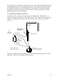
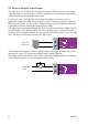
2.3 Power Supply
The RM-90 module can be powered from a 10 – 30VDC power supply. The power supply
should be rated at 1 Amp and be CSA Certified Class 2. The negative side of the supply
should be connected to a good “ground” point for surge protection. The supply negative
is connected to the unit case internally.
The positive side of the supply must not
be connected to earth. The DC supply may
be a floating supply or negatively grounded.
The power requirements of the RM-90 unit
is 280mA @ 12V or 150mA @ 24VDC.
This is inclusive of radio and Ethernet ports
active, & serial port plugged in. Transmission
current (1W RF) is nominally 500mA at 12V, 250mA at 24VDC.
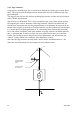
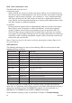
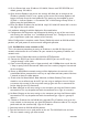
2.4 Serial Connections
2.4.1 RS-232 Serial Port
The serial port is a 9 pin DB9 female and provides for connection to a host device as
well as a PC terminal for configuration, field testing and for factory testing. The RM-90
is configured as DCE equip-
ment with the pinouts detailed
below.
Hardware handshaking using
the CTS/RTS lines is provided.
The CTS/RTS lines may be
used to reflect the status of
the local unit’s input buffer, or
may be configured to reflect
the status of CTS/RTS lines at
the remote site. The RM-90
does not support XON/XOFF.
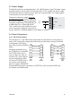
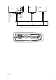
Example cable drawings for connection to a DTE host (a PC) or another DCE hosts
(or modem) are detailed above.
T
7
6
"
8DB
9>D
GB".%
&%"(%
K98
G
H")-*
HJEEAN
97.
B6A:
9I:=DHI
97.
;:B6A:
97.
B6A:
98:=DHI
97.
B6A:
G9
I9
H<
GIH
8IH
9HG
9IG
989
G9
I9
H<
GIH
8IH
9HG
9IG
989
G9
I9
H<
GIH
8IH
9HG
9IG
989
G9
I9
H<
GIH
8IH
9HG
9IG
989
'
(
*
,
-
'
(
*
,
-
+
)
&
'
(
*
,
-
'
(
*
,
-
+
)
&
GB".% GB".%