OPERATOR’S MANUAL MODELS 05TCG 10TCG 20TCG 30TCG 50TCG KEEP THESE INSTRUCTIONS WITH THE TRANSCUBE
USER'S NOTICE t The TransCube was designed for the transport of diesel fuel - UN 1202 / UN 1993. t It is a double wall Intermediate Bulk Container (IBC). t Regulation size placards must be on all 4 sides of the TransCube or its means of transport. t The TransCube was manufactured to the United Nations speci fications (eg. 49 CFRCode of Production) tested and certified as a UN Standard Mobile IBC, 31 AY Packing Group III.
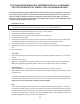
THE TRANSCUBE MOBILE IBC (INTERMEDIATE BULK CONTAINER) FOR THE TRANSPORT OF DIESEL FUEL ON CANADIAN ROADS. The UN (United Nations) approved Mobile IBC complies with the following regulations: the UK carriage of dangerous goods by road requirements and the European agreement concerning the international carriage of dangerous goods by road (ADR), US DOT and Transport USA.
MANUFACTURER LIMITED WARRANTY This warranty is in substitution of every warranty as to quality fitness or description expressed or implied by statute, common law or custom. WESTERN products are fully guaranteed for a period of one year from the date of purchase against faulty workmanship or material. Faulty products should be returned by the customer to the supplier.
SERIAL NUM ER LOCATION Always give your dealer the serial number of your Western Environmental TransCube when ordering parts or requesting service or other information. The serial number plate is located where indicated. easy reference.
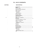
TA LE OF CONTENTS SECTION . . . . . . . . . . 3 . . . . . . . . . . DESCRIPTION Introduction ........................................................ Safety .................................................................... General Safety....................................................... Equipment Safety Guidelines ................................ Safety Training....................................................... Safety Signs ..........................................................
INTRODUCTION Congratulations on your choice of a TransCube to complement your refueling or transporting operation. This equipment has been designed and manufactured to meet the needs of a discriminating buyer for ef cient refueling of equipment or transporting of fuel.
SAFETY SAFETY ALERT SYM OL This Safety Alert symbol means ATTENTION ECOME ALERT YOUR SAFETY IS INVOLVED The Safety Alert symbol identifies important safety messages on the TransCube and in the manual. When you see this symbol, be alert to the possibility of personal in ury or death. Follow the instructions in the safety message. Why is SAFETY important to you 3 i Reasons SIGNAL WORDS Note the use of the signal words DANGER, WARNING and CAUTION with the safety messages.
SAFETY 2.1 GENERAL SAFETY YOU are responsible for the SAFE operation and maintenance of your TransCube. YOU must ensure that you and anyone else who is going to use, maintain or work around the TransCube be familiar with the using and maintenance procedures and related SAFETY information contained in this manual. This manual will take you step-bystep through your working day and alerts you to all good safety practices that should be used while using the TransCube. 1.
2.2 EQUIPMENT SAFETY GUIDELINES 1. Safety of the operator and bystanders is one of the main concerns in designing and developing a machine. However, every year many accidents occur which could have been avoided by a few seconds of thought and a more careful approach to handling equipment. You, the operator, can avoid many accidents by observing the following precautions in this section.
2.3 SAFETY TRAINING 2.4 SAFETY SIGNS 1. Safety is a primary concern in the design and manufacture of our products. Unfortunately, our efforts to provide safe equipment can be wiped out by a single careless act of an operator or bystander. 1. Keep safety signs clean and legible at all times. 2.
2.5 PREPARATION 1. Never use the unit until you have read and completely understand this manual and each of the Safety Messages found on the safety signs on the unit. 2. Personal protection equipment including hard hat, safety glasses, safety shoes, and gloves are recommended during assembly, installation, operation, adjustment, maintaining, repairing, removal, cleaning, or moving the unit. Do not allow long hair, loose fitting clothing or jewelry to be around equipment. 3.
2.8 TRANSPORT SAFETY 2.9 MAINTENANCE SAFETY 1. Read and follow the Operator's Manual before using the TransCube. 1. Good maintenance is your responsibility. Poor maintenance is an invitation to trouble. 2. Review and follow the User's Notice inside the lid before using. 2. Follow good shop practices. 3. Be familiar with the requirements of "Transport of Dangerous Goods" regulations and follow them. 4. Train all drivers about the requirements of transporting an Intermediate Bulk Container (IBC).
2.10 SIGN-OFF FORM The equipment provider follows the general Safety Standards specified by the UN/DOT for the transport of diesel fuel. Anyone who will be using and/or maintaining the tank must read and clearly understand ALL Safety, Usage and Maintenance information presented in this manual. Do not use or allow anyone else to use this tank until such information has been reviewed. Annually review this information before the season start-up.
3 SAFETY SIGN LOCATIONS The types of safety signs and locations on the equipment are shown in the illustrations that follow. Good safety requires that you familiarize yourself with the various safety signs, the type of warning and the area, or particular function related to that area, that requires your SAFETY AWARENESS. • Think SAFETY! Work SAFELY! B A A OPERATING INSTRUCTIONS • Read "Users Notice" and Operator's Manual before using fuel tank.
4 OPERATION OPERATING SAFETY • • Please remember it is important that you read and heed the safety signs on the TransCube. Clean or replace all safety signs if they cannot be clearly read and understood. They are there for your safety, as well as the safety of others. The safe use of this tank is strictly up to you, the operator. Use only for the transport of diesel fuel for refueling equipment or stand-by generators. • Keep the tank level when filling. • Fill only with a hand-held trigger nozzle.
. MACHINE COMPONENTS D The TransCube is a double-walled tank for holding, transferring or transporting fuel. The fuel tank mounts inside the outer tank. The TransCube is designed so the outer tank is large enough to hold all the uid should the inner fuel tank break, crack or leak capacity in the interstice . O H W E L M W F R P G C Close and lock the lid when trans porting or not using the tank. The inch ll plug is located on the inner tank along with the psi fusible plug for venting.
4.3 MACHINE BREAK-IN Although there are no operational restrictions on the TransCube when used for the first time, it is recommended that the following mechanical items be checked: A. After Using for 1 and 5 Hours: 1. Check all nuts, bolts and other fasteners. Tighten to their specified torque level. 2. Check that the fuel lines and connections are in good condition and there are no leaks. 3. Check that the electrical system is in good condition.
4.5 CONTROLS The TransCube is designed and built with components that allow for easy and convenient transporting, filling and transferring fuel. Each operator should be trained in TransCube operation before using and the controls on the unit. They must also be required to know all the legal and regulatory regulations relating to the transporting and handling of fuel. Review the controls on the unit prior to using and as a part of the regular training program: 1.
3. Fuel Gauge: This gauge shows the amount of fuel in the tank. Watch this gauge when filling the tank. Do not fill more than 95% to prevent spillage and allow for expansion. 4. Fuel Meter (Optional): This meter measures the volume of fuel being transferred by the hose and nozzle. Depress the reset button on top to zero the gauge when required. 3 4 Fig. 4 FUEL METER (OPTIONAL) 5.
. FIELD USE OPERATING SAFETY Please remember it is important that you read and heed the safety signs on the TransCube. Clean or replace all safety signs if they cannot be clearly read and understood. They are there for your safety, as well as the safety of others. The safe use of this tank is strictly up to you, the operator. Use only for the transport of diesel fuel for refueling equipment or stand-by generators. Do not over fill. 95% is the maximum legal limit.
2. Venting: a. Each tank is designed with a stainless steel and polyethylene pressure/vacuum relief vent with elastomer seals set at 3 psi. Maintain in good condition. Replace vent if damaged in any way. Replace vent at the 60 month test. b b. The fill cap is designed with a 3 inch NPS stainless steel fusible (viton) ring that would melt when the temperature reaches 250°F. Keep it in good condition. Replace cap if it is damaged in any way. c.
3. Securement for Transport: The frame is designed with brackets on the top corners to anchor the tie-downs when transporting. Do not transport TransCube unless it is securely tied-down to the vehicle frame. The TransCube must be securely attached to its means of transport, be it a custom trailer, flat-bed trailer or skid. Brackets Schematic Trailer Fig.
4. Filling TransCube: A 3 inch fill cap is located on the top of the tank and is used to fill the tank. Turn the cap to open the tank for filling. Open the cap slowly to release any build-up of pressure due to extreme temperatures. Close and tighten cap when filling is completed. Follow this procedure when filling tank: b a. Level the tank or the vehicle that it is mounted on. b. Loosen fill cap and lay to the side.
5. Closure for Transport: The TransCube must be securely closed prior to moving or transporting to minimize the chance of spilling fuel. Follow this procedure when preparing for transport: a. Turn the pump off by moving the control lever down. Pump Off IMPORTANT The closure systems nearest to the contents of the IBC should be closed first. b. Turn the generator port valves off. c. Close and tighten fill cap. d.
6. Generator Standby: The TransCube is designed to be used to provide fuel to generator sets or any other power unit requiring fuel. Follow this procedure when connecting as a fuel supply to an engine: a. Place TransCube in a level area adjacent to the engine requiring fuel. b. Install quick couplers into the tank outlets appropriate for your application. The feed or return ports are marked with directional arrows. Valves NOTE Use teflon tape on the threads to prevent leaking at the connection. c.
7. Refueling: The TransCube works well as a tank to refuel other tanks, machines or equipment. Review the pump manual prior to using the pump. Follow this procedure when refueling: a. Refer to Step 4 (pg. 18) "Filling TransCube". b. Transport the TransCube to the refueling area. c. Unlock and open hatch lid. d. Pull out refueling hose and nozzle. e. Extend it to the tank needing to be refueled. f. Fig. 12 FILLING TANK Connect a power supply to the pump (minimum 20 amp rating). g. Turn the pump on. h.
8. Fuel Gauge: The TransCube is designed with a gauge that displays the amount of fuel in the tank. Always watch the gage when filling the tank to prevent over-filling. The lid is designed with an access hole above the gauge to allow for monitoring the fuel level without the need to open the lid. Gauge Access Hole Fig. 14 FUEL GAUGE 9. Forklifts: The base of the TransCube is designed with pockets on all sides to allow access for the forks of a forklift.
10. Additional Outlets: The top of the tank is designed with extra outlets to allow additional engines or machines to use the tank as a source for fuel. Install the feed and return lines, down tube check valve, strainer and return port into the outlets. Mount shut-off valves to each line to allow the line to be turned off when required. Fig. 16 ADDITIONAL OUTLETS 11. Manway Access Cover: The top is designed with a cover to provide access to the inside of the tank when required.
12. Records: • Each owner or operator is responsible to obtain records from the periodic inspections and re-testing of the IBC TransCube and keep them with the unit. Place your record and operator's manual in the vinyl sleeve provided on the shelf above the inner tank. • Keep the records available with the unit and make them available to Government Representatives or Inspectors on site when requested. • A Record Card is provided with the Documentation package to record the compulsory Fig.
15. Storage: • The frame of the TransCube is designed with the structural strength to allow stacking 2 high when full and 3 high when empty. Always mate the corner brackets together to stabilize the pile. • Use only a hoist or forklift with the required lift capacity to raise, lower or stack the tanks. Stored Forklift Fig.
16. Power Source: • When a pump is fitted, the unit comes from the factory with a power cord to the pump. It is recommended that 20 amp rated battery clamps on the power cord to attach to battery terminals on the equipment being refueled (12 volt pump only). Fig. 20 POWER CORD 17. Monitoring: The best results are obtained when the TransCube is monitored, inspected, checked and tested per this recommended list. Keep and maintain these records. a.
c. Wee ly and efore Transportin Visually check the interstice bund to verify that there have been no leaks from the primary tank or any spills during fuel transfers. If it has any sludge or liquid in it, hand pump it into an approved container, seal it and dispose of it in accordance with local regulations. Do not pour on the Fi . ground or put in drains.
. CLEANING Each owner and user of the TransCube should review this manual as part of the regular training and review procedure. Follow all instructions. . Remove corner sockets, edging strip and install lifting eyes. . With the inner tank emptied of fuel, lift it out using the lifting eyes. . Clean the inside of the outer tank bund . Remove all debris and liquids. With Tan Empty . Remove the corner lifting stacking sockets.
RECORD FORM Use this form to keep track of all tank inspections and testing. Make copies of the next records.
30
6 TROUBLE SHOOTING The TransCube is a double walled tank for transporting diesel fuel from one location to another. It is a simple and reliable system that requires minimal maintenance. In the following section, we have listed many of the problems, causes and solutions to the problems that you may encounter. If you encounter a problem that is difficult to solve, even after having read through this trouble shooting section, please call your local Western distributor or dealer.
32 220 440 660 1040 10TCG 20TCG 30TCG 50TCG 1247 792 528 4725 3000 2000 90 1/2" (2300) 59 1/8" (1500) 52" (1320) 86 1/4" (2190) 45 1/4" (1155) 52" (1320) 45 1/4" (1155) 45 1/4" (1155) 52" (1320) 45 1/4" (1155) 45 1/4" (1155) 33" (838) 12235 LBS (5550) 90 1/2" (2300) 90 1/2" (2300) 52" (1320) 7765 LBS (3522) 5574 LBS (2528) 2994 LBS (1358) 1901 LBS (862) SPECIFICATIONS SUBJECT TO CHANGE WITHOUT NOTICE 3567 LBS (1618) 2153 LBS (972) 1825 LBS (828) 1118 LBS (508) 965 LBS (437) DIM
7.2 BOLT TORQUE CHECKING BOLT TORQUE The tables shown below give correct torque values for various bolts and capscrews. Tighten all bolts to the torques specified in chart unless otherwise noted. Check tightness of bolts periodically, using bolt torque chart as a guide. Replace hardware with the same strength bolt. ENGLISH TORQUE SPECIFICATIONS Bolt Torque* Bolt SAE 5 SAE 2 SAE 8 Diameter (N.m) (lb-ft) (N.m) (lb-ft) (N.
7.3 HYDRAULIC FITTING TORQUE TIGHTENING FLARE TYPE TUBE FITTINGS * 1. Check flare and flare seat for defects that might cause leakage. 2. Align tube with fitting before tightening. 3. Lubricate connection and hand tighten swivel nut until snug. 4. To prevent twisting the tube(s), use two wrenches. Place one wrench on the connector body and with the second tighten the swivel nut to the toque shown. * The torque values shown are based on lubricated connections as in reassembly.
. TYPICAL UN TEST CERTIFICATE 3
INDE I S PAGE Introduction...................................................... O Operation....................................................... Cleaning ................................................... Controls .................................................... Field Use .................................................. Machine reak-In ..................................... Machine Components............................... re-Operation Checklist ...........................
ISSUE DATE: MARCH 2010 PART #: TC0213US Western Global Inc. WESTERN INTERNATIONAL, INC. 290 Quarry Road 18 Lois Street Milford, CT 06460 Norwalk, CT 06851 T | 203-847-4300 F | 203-847-4310 T: 203 847 4300 F: 203 847 4310 E | info@western.us.com E: info@western.us.com W| www.transcube.